System and method for adjusting the trip characteristics of a circuit breaker

a circuit breaker and trip characteristic technology, applied in the field of electrical systems, can solve problems such as ineffective adjustment of trip characteristics of circuit breaker

Active Publication Date: 2015-06-11
EATON INTELLIGENT POWER LTD
View PDF8 Cites 37 Cited by
  • Summary
  • Abstract
  • Description
  • Claims
  • Application Information

AI Technical Summary

Problems solved by technology

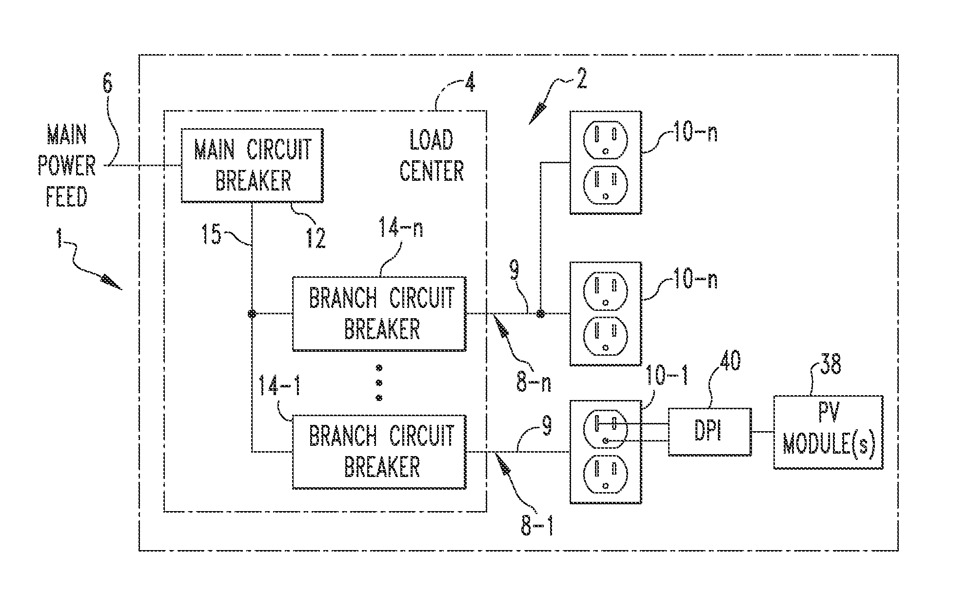
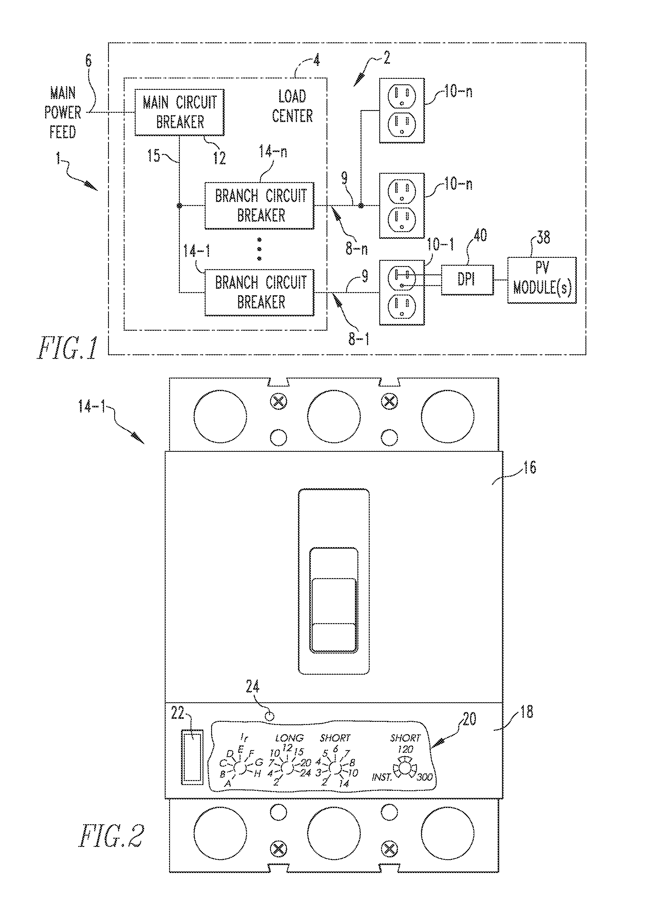
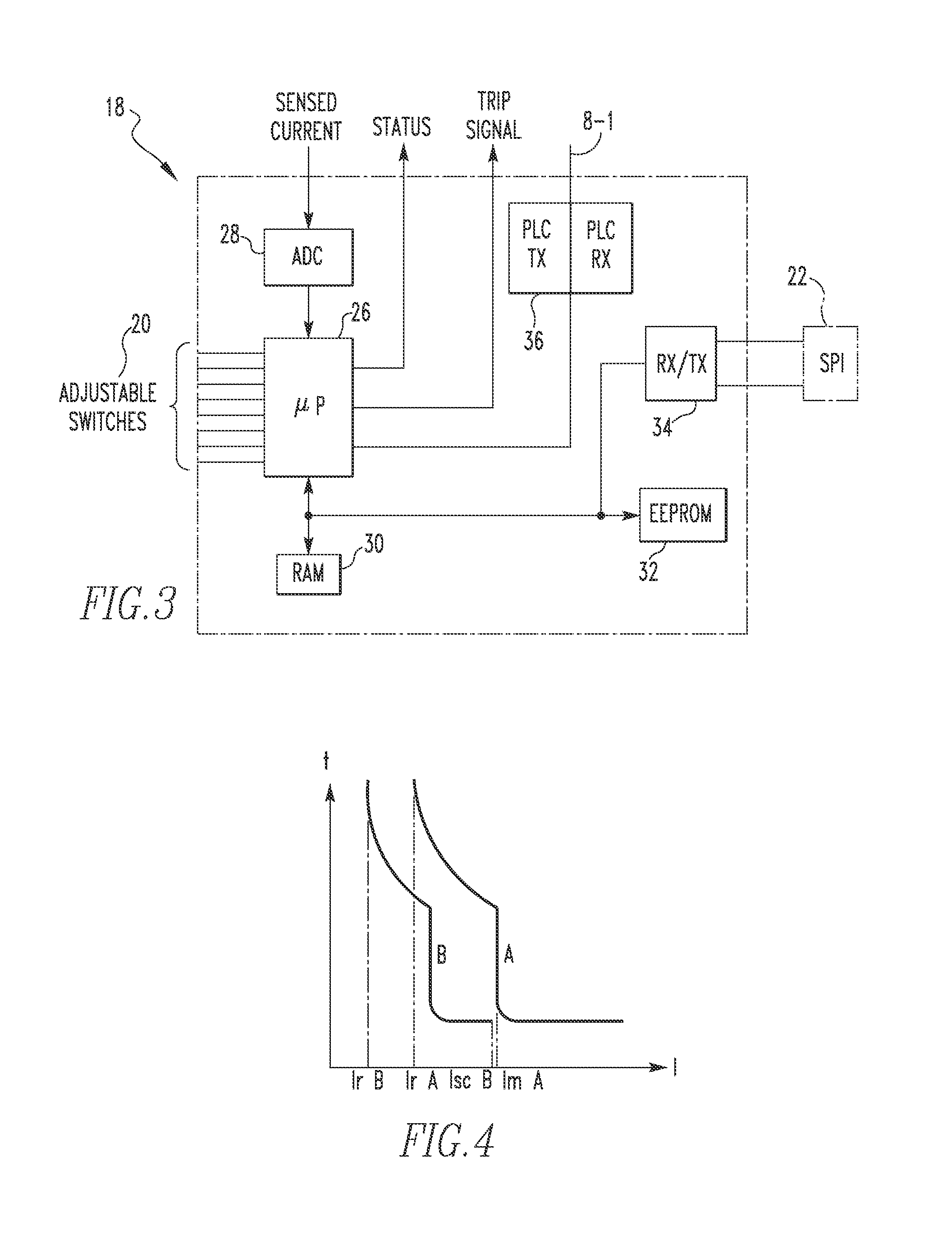
The problem is that in such a configuration, the trip curve of the branch circuit breaker, which determines the amount of time required for the circuit breaker to trip at a given overcurrent level, needs to be adjusted to compensate for the distributed power sources being present on the same non-dedicated circuit (e.g., plugged into receptacles).
Currently, there is no efficient way for making such adjustments.

Method used


Image

  • System and method for adjusting the trip characteristics of a circuit breaker
  • System and method for adjusting the trip characteristics of a circuit breaker
  • System and method for adjusting the trip characteristics of a circuit breaker

Examples


Embodiment Construction

[0020]Directional phrases used herein, such as, for example, left, right, front, back, top, bottom and derivatives thereof, relate to the orientation of the elements shown in the drawings and are not limiting upon the claims unless expressly recited therein.

[0021]As employed herein, the term “number” shall mean one or an integer greater than one (i.e., a plurality).

[0022]As employed herein, the statement that two or more parts are “coupled” together shall mean that the parts are joined together either directly or joined through one or more intermediate parts.

[0023]As employed herein, the term “default ampacity rating” shall mean the maximum continuous current a circuit breaker is designed to carry without tripping.

[0024]As employed herein, the term “set ampacity rating” shall mean the maximum continuous current that a circuit breaker can carry without tripping for a given continuous current setting. As will be appreciated, “set ampacity rating” applies to those circuit breakers that...


PUM


Abstract

An electrical system includes (1) a distributed power source device structured to generate: (i) AC power, and (ii) a signal indicating an amount of current being produced by the distributed power source device, and (2) a circuit breaker having set trip characteristics coupled to distributed power source device, wherein the circuit breaker is structured to receive the signal and adjust the set trip characteristics (e.g., the trip curve) based on at least the signal from the distributed power source device.

Description

BACKGROUND[0001]1. Field[0002]The disclosed concept relates generally to electrical systems that employ distributed power sources, and, in particular, to a system and method for adjusting the trip characteristics of a circuit breaker in an electrical system having current limited distributed power sources, such as a branch circuit that includes one or more current limited distributed power sources and, in some instances, one or more loads.[0003]2. Background Information[0004]A distributed power source is a small-scale power generation mechanism used to provide an alternative to or an enhancement of the traditional electric power system. Distributed power sources include, for example and without limitation, photovoltaic (PV) modules, wind turbine modules, backup generators, energy storage, and uninterruptible power supplies.[0005]The National Electric Code (NEC) presently requires a distributed power source to be located on a dedicated branch circuit (i.e. without any loads on the sa...

Claims


Application Information

Patent Timeline
Patent Type & Authority Applications(United States)
IPC IPC(8): H01H77/10H04B3/54
CPCH04B3/54H01H77/10H02H3/093H02J13/00007H02J2310/12H02J2300/24H02J3/381H02J13/00004H02J13/0004H02J3/14Y02E10/56Y04S40/121Y04S20/14Y02B90/20Y02E60/00Y04S10/123Y02E40/70H02H3/08H01H83/20H02H3/38
Inventor LUEBKE, CHARLES J.SCHOEPF, THOMAS J.
Owner EATON INTELLIGENT POWER LTD
Why Eureka
Try Eureka