Stand-alone electrical system for large motor loads

a technology for motor loads and electrical systems, applied in the field of electric power systems, can solve the problems of high current flow toward short-circuits, and achieve the effect of minimizing the impact of short-circuits

Active Publication Date: 2008-06-17
CONOCOPHILLIPS CO
View PDF13 Cites 125 Cited by
  • Summary
  • Abstract
  • Description
  • Claims
  • Application Information

AI Technical Summary

Benefits of technology

[0010]The motors are expected to be the largest loads of the LNG facility. With this in mind, each generator is preferably sized to provide power for between one and two of the motors. A quantity of generators is preferably determined by an engineer according to characteristics of the generators and the loads. In addition, the quantity of generators preferably includes at least one more generator than that required by the total power consumed in order to accommodate maintenance or tripping of any of the generators. This advantageously allows the system to be used with smaller generators, rather than relying on larger, more expensive, and more difficult to maintain generators. Similarly, the primary bus preferably has a rating sufficient to handle the power requirements of between one and two of the motors.
[0012]The system may also incorporate a special-use bus connected to the primary bus through one or more variable frequency drives (VFD). For example, one or more of the motors may be disconnected from the primary bus and connected to the special-use bus. Then, that motor may be slowly ramped up using the VFD. Once that motor is synchronized with the primary bus, that motor may be re-connected to the primary bus. In this manner, the special-use bus may be used to start the motors with minimal impact on the primary bus and the rest of the LNG facility.
[0014]Thus, by distributing the generators and the loads along the primary bus, lesser rated generators and bus components may be used, thereby overcoming the problems of the prior art. Specifically, the system of the present invention overcomes the limitations of the primary bus' current carrying capacity while generating the power at a voltage level required by the loads, thereby not requiring the use of costly transformers.
[0018]Finally, the engineer determines where each ISCL should be placed. Each ISCL should be placed to prevent any short-circuit from exceeding a short-circuit current rating of the primary bus. For example, the generators are able to produce a specified short-circuit current. In addition, any of the motors that are running may also produce short-circuit current. Since the system includes several generators and motors, a total short-circuit current may be very high, and beyond the primary bus's momentary rating for short-circuit current. However, by placing the ISCLs along the primary bus between the generators, the engineer prevents multiple generators and motors from cooperating in response to the short-circuit. Thus, the primary bus need only be rated to handle the short-circuit current from one of the generators and one of the motors.
[0019]As discussed above, the ISCLs may break down the primary bus into several sub-buses. Thus, the engineer may also locate ISCLs with this in mind. For example, the engineer may decide to place the ISCLs around, or in series with, large loads in an effort to minimize any impact a short-circuit associated with those loads might have on the rest of the system.

Problems solved by technology

A catastrophic failure, such as a short-circuit, would likely cause extremely high current flow toward the short-circuit.

Method used


Image

  • Stand-alone electrical system for large motor loads
  • Stand-alone electrical system for large motor loads
  • Stand-alone electrical system for large motor loads

Examples


Embodiment Construction

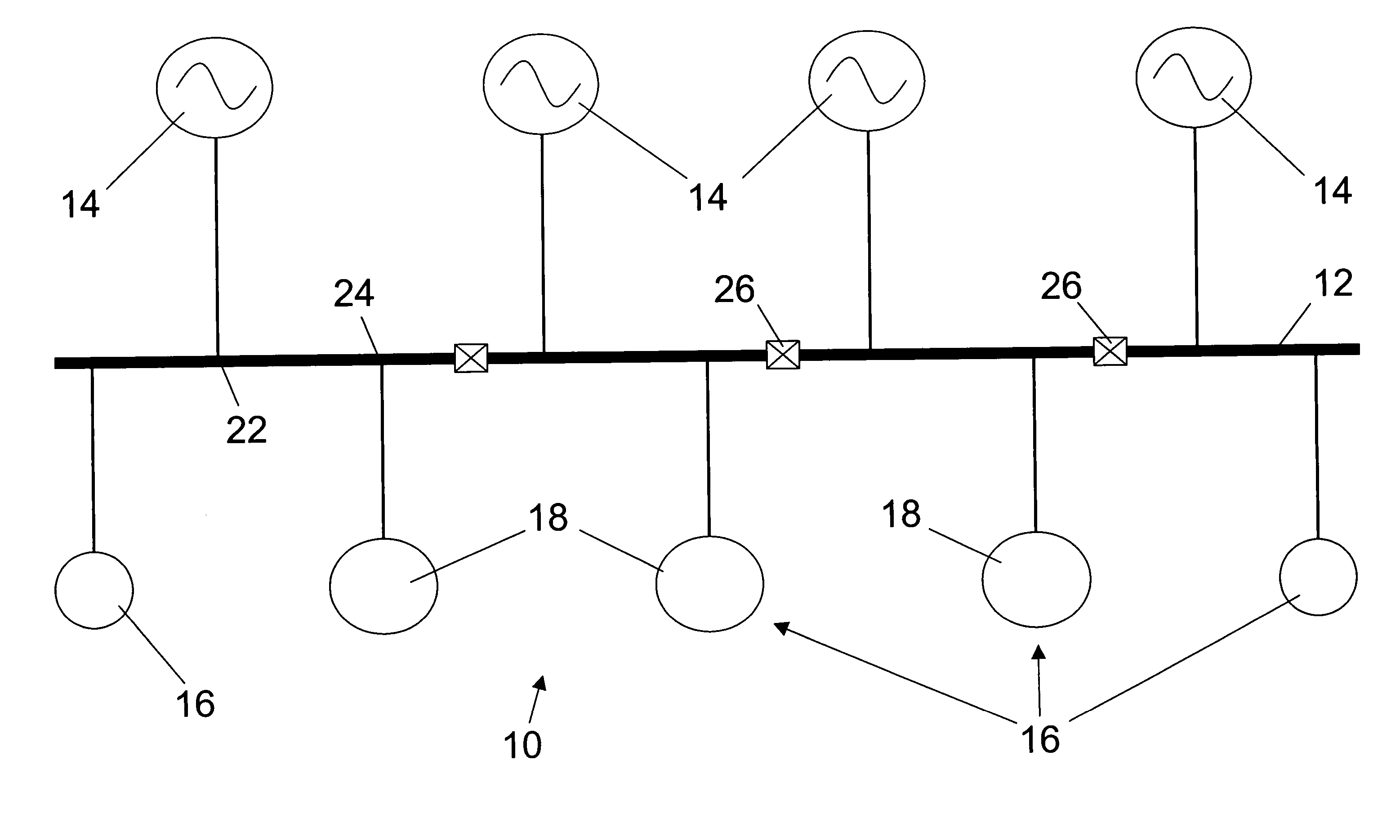
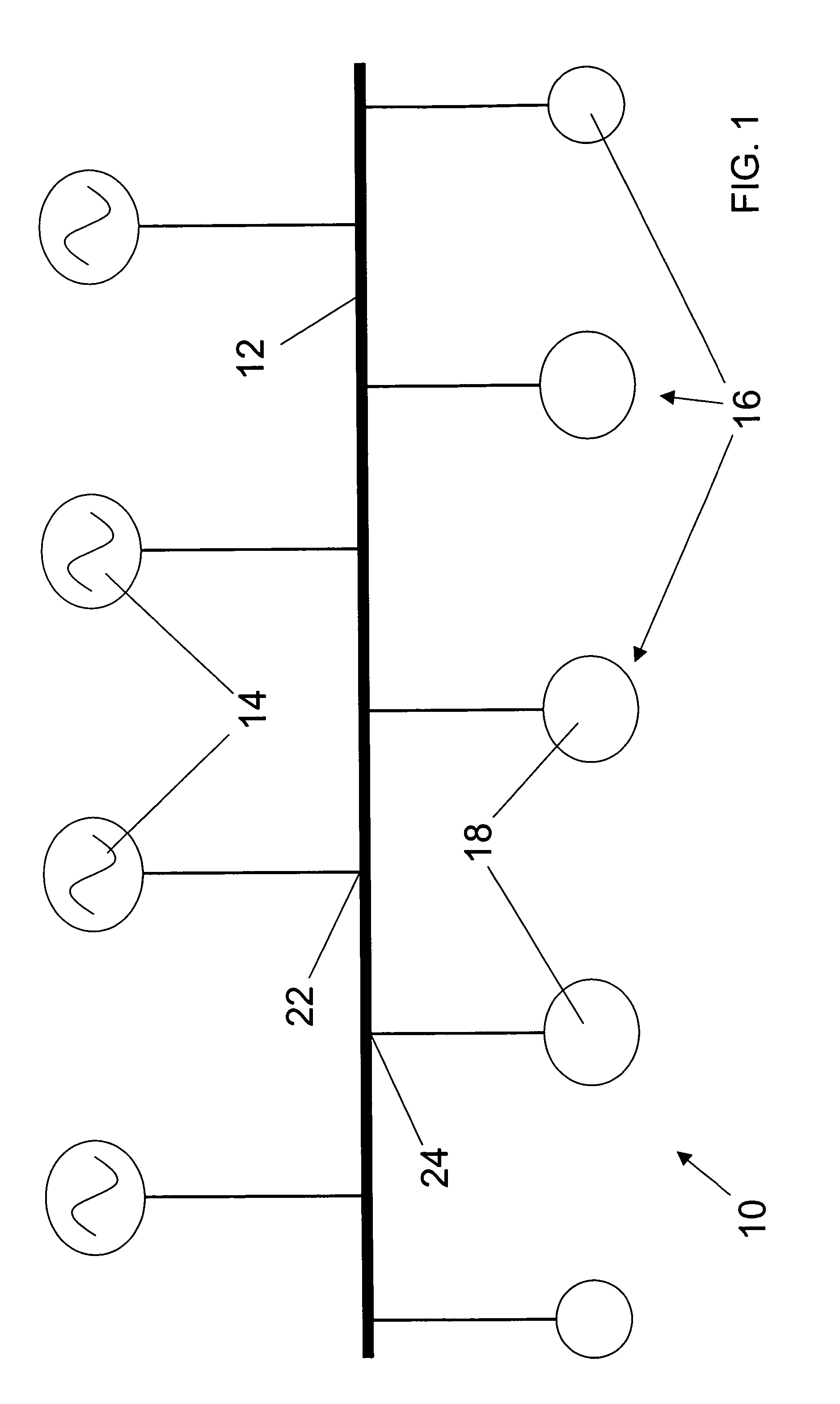
[0032]Referring to FIG. 1, the preferred electrical power system 10 constructed in accordance with a preferred embodiment of the present invention is illustrated as part of a Liquified Natural Gas (LNG) facility. Preferably, the LNG facility is a cascaded-type LNG facility employing at least one open refrigeration cycle. For example, the LNG facility may be similar to that described in U.S. patent application Ser. No. 10 / 286,292, the entire disclosure of which is incorporated herein by reference. The system 10 broadly comprises a primary bus 12 connected between a plurality of generators 14 and a plurality of electrical loads 16, such as electrical compressor motors 18 used in the LNG facility. The LNG facility typically uses compressors in converting natural gas from a gaseous state to a liquid state, otherwise known as LNG. As a result, the motors 18 are typically the LNG facility's biggest power consumer.

[0033]While the compressors may be driven directly by gas turbines, the comp...


PUM

PropertyMeasurementUnit
voltageaaaaaaaaaa
voltageaaaaaaaaaa
total poweraaaaaaaaaa

Abstract

An electrical power system that can be used to interconnect a plurality of generators to a plurality to loads while being rated at less than a total power consumed. The system is preferably used to distribute power for a Liquefied Natural Gas (LNG) facility. The system broadly comprises a primary bus connected between the generators and the loads, such as electrical compressor motors used in the LNG facility. The generators and the loads are arranged along the primary bus in order to distribute the power from the generators to the loads, without overloading the primary bus.

Description

BACKGROUND OF THE INVENTION[0001]1. Field of the Invention[0002]The present invention relates to electrical power systems. More particularly, the present invention relates to an electrical power system that can be used to interconnect a plurality of generators to a plurality of loads while being rated at less than a total power consumed.[0003]2. Description of Prior Art[0004]Power distribution buses are commonly used to distribute power from sources, such as generators and / or electrical power providers, to electrical loads. As a total power consumed is increased, a rating of a distribution bus must also be increased. In other words, bus ratings must be increased to handle an increase in total power consumed flowing through a bus.[0005]However, there are practical limits on rating increases for conventional buses. For example, skin effect limits a bus bar's current carrying capacity. Additionally, components for higher rated buses are very expensive and occupy a large space. Therefor...

Claims


Application Information

Patent Timeline
Patent Type & Authority Patents(United States)
IPC IPC(8): H02G5/06F25J1/02H01B9/06H02J3/46H02JH02J1/00H02J3/00H02J3/06H02J3/38
CPCH02J3/005H02J3/06H02J3/38H02J3/007
Inventor SEIVER, JOHN R.
Owner CONOCOPHILLIPS CO
Why Eureka
Try Eureka