Multi-grounded neutral electrical isolation between utility secondary low-voltage power service and high-voltage transmission structures

a technology of electrical isolation circuit and utility secondary, applied in the direction of overvoltage protection resistor, emergency protective arrangement for limiting excess voltage/current, and arrangements responsive to excess voltage, etc., can solve the problem of hazard of electrocution and/or ignition of any interconnected public utility customer, affecting the isolation of the distribution grid from the cell site, and causing harm to any nearby conductor. the effect of common-mode voltages and easy and economical implementation

Inactive Publication Date: 2000-08-22
WILSON HAMILTON & SEVERINO ENGINEERS LLC AN ARIZONA LLC +1
View PDF2 Cites 8 Cited by
  • Summary
  • Abstract
  • Description
  • Claims
  • Application Information

AI Technical Summary

Benefits of technology

A final objective is a system that can be implemented easily and economically according to the above stated criteria.
Therefore, according to these and other objectives, the multi-grounded neutral electrical isolation system of this invention consists of two standard distribution transformers separated by a distance greater than the zone of influence corresponding to the maximum expected ground potential rise at the PCS cell site. The primary winding of the first transformer is connected to the utility's low-voltage distribution system and is grounded through the network's ground. The secondary winding is connected to the primary winding of the second transformer through a high-voltage non-shielded insulated conductor and the frames of the two transformers are kept electrically and physically isolated. The secondary winding of the second transformer energizes the PCS cell site and shares its ground connection, which is also common to the adjacent high-voltage transmission tower. All neutrals are grounded through their respective grounding systems. Finally, the second transformer is selected with a basic insulation level (BIL) rating sufficient to withstand the maximum ground potential rise expected to occur at the cell site as a result of a fault or a lightening discharge at the high-voltage transmission tower. Thus, by separating the two transformers by a distance at least equal to the zone of influence corresponding to such a GPR, the isolation of the distribution grid from the cell site is ensured. Moreover, the BIL rating of the second transformer protects the transmission grid from a sudden potential rise due to a fault in the transformer's insulation. Obviously, such rating of the transformer is judiciously selected to provide the desired level of protection.

Problems solved by technology

PCS cell sites typically require an antenna reaching 15 to 45 meters high from ground level and regulatory impediments often prevent the erection of support structures for such antennae in populated areas.
This can cause severe damage to equipment and cables, and possibly represent a hazard for electrocution and / or ignition for any interconnected public utility customers.
Additionally, because the multi-grounded neutral can carry a significant fraction of the fault current, it can induce detrimental common-mode voltages in any nearby conductor.
The main threat to the public is through the multi-grounded neutral interconnection.
The source of the problem is the possibility that a large GPR can occur as a result of a power fault on the high-voltage transmission line.

Method used


Image

  • Multi-grounded neutral electrical isolation between utility secondary low-voltage power service and high-voltage transmission structures
  • Multi-grounded neutral electrical isolation between utility secondary low-voltage power service and high-voltage transmission structures
  • Multi-grounded neutral electrical isolation between utility secondary low-voltage power service and high-voltage transmission structures

Examples


Embodiment Construction

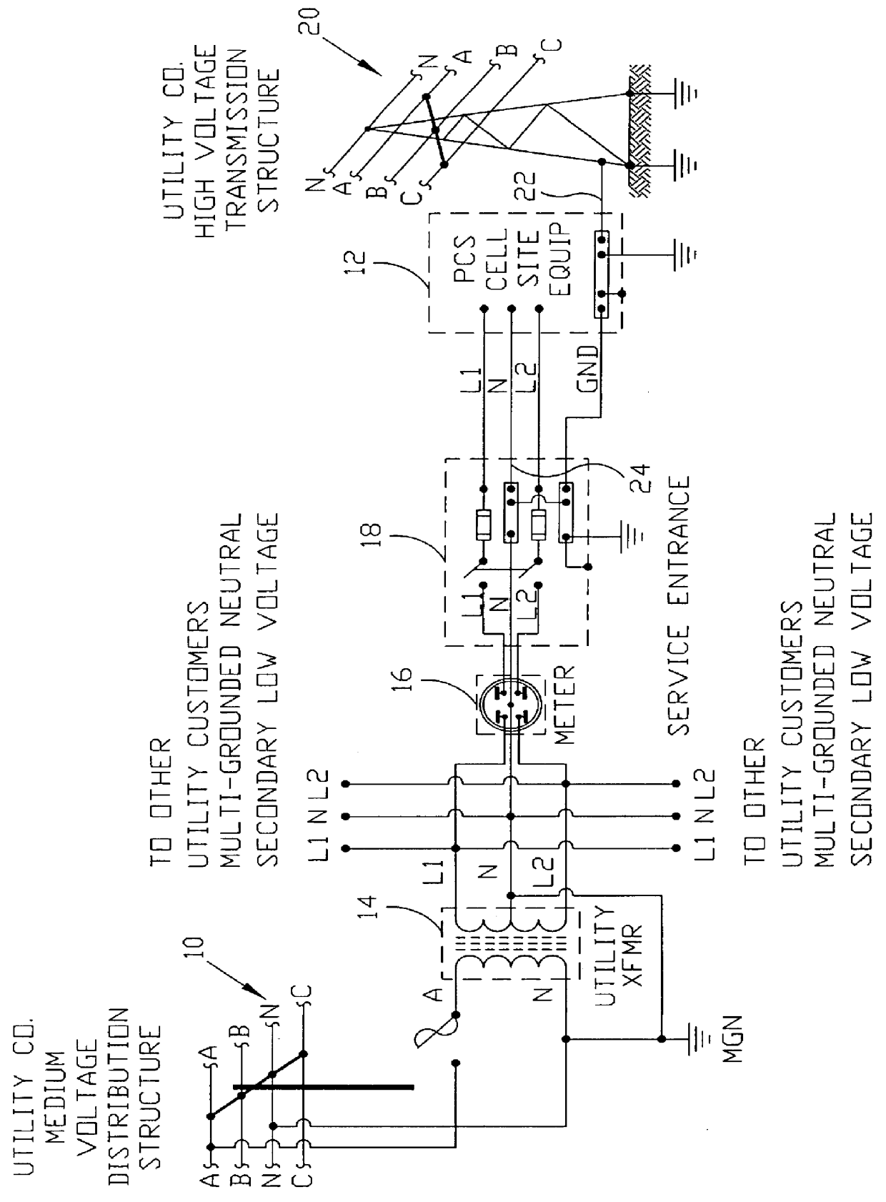
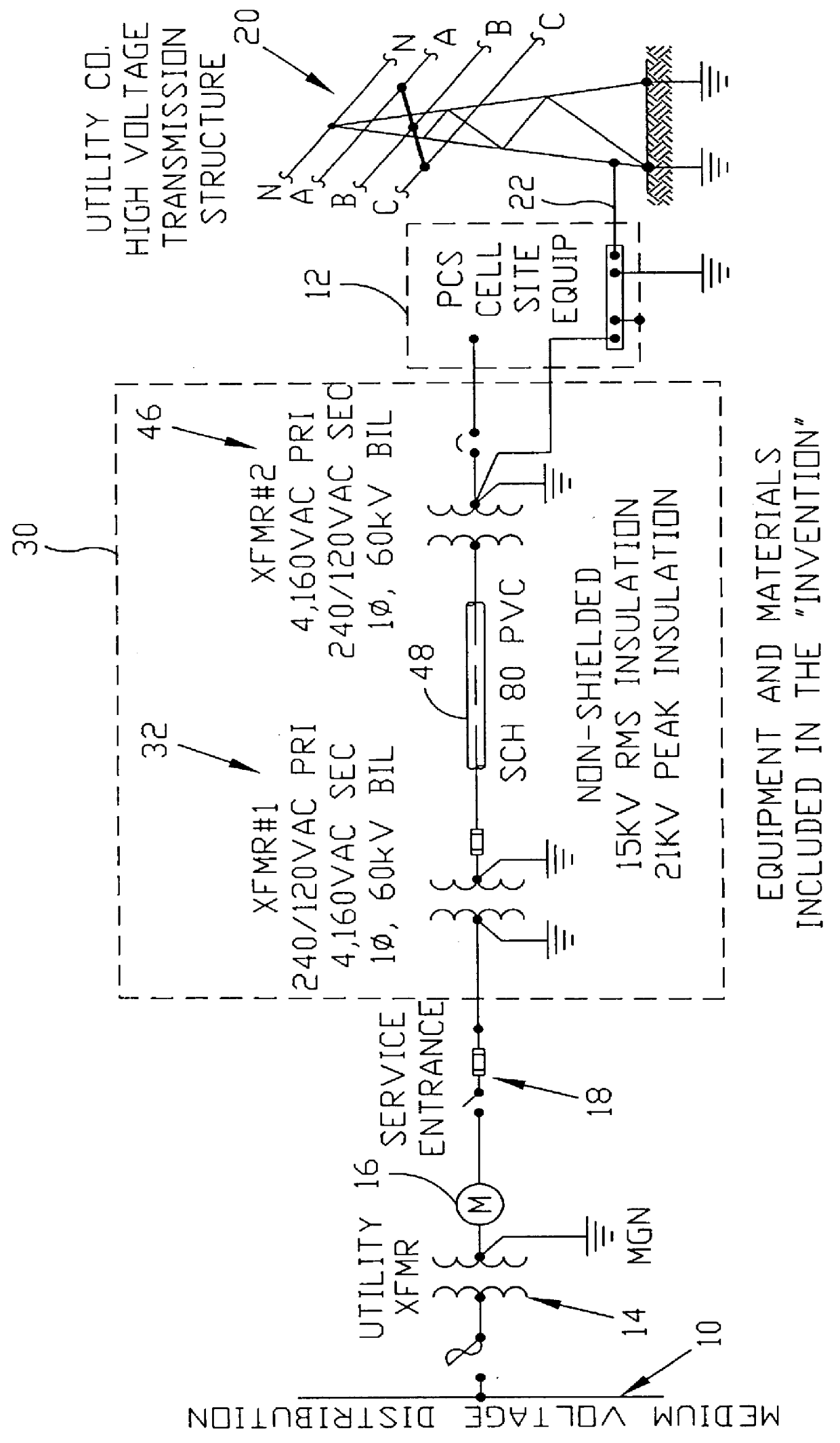
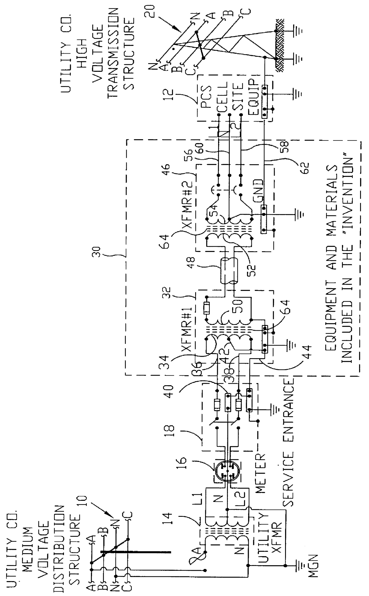
The heart of this invention lies in the recognition that the potential problem of a sudden ground potential rise spreading to a distribution network from a personal-communication-system cell site erected in the vicinity of a high-voltage transmission tower can be corrected by decoupling their grounding systems. This can be achieved rather economically with conventional equipment by exploiting the electrical separation existing between primary and secondary windings of a transformer and the built-in basic insulation level provided through conventional manufacture, which can be used advantageously to ensure isolation of the primary winding under the effect of any predetermined voltage rise applied to the secondary winding through its ground connection.

Referring to the drawings, wherein like parts are designated throughout with like numerals and symbols, FIGS. 2 and 3 illustrate in one-line and connection diagrams, respectively, of the preferred embodiment of an isolation system 30 acc...


PUM


Abstract

A multi-grounded neutral electrical isolation system for a personal-communication-system cell site consists of two standard distribution transformers separated by a distance greater than the zone of influence corresponding to the maximum expected ground potential rise at the PCS cell site. The primary winding of the first transformer is connected to the utility's low-voltage distribution system and is grounded through the network's ground. The secondary winding is connected to the primary winding of the second transformer through a high-voltage non-shielded insulated conductor and the frames of the two transformers are kept electrically isolated. The secondary winding of the second transformer energizes the PCS cell site and shares its ground connection, which is also common to the adjacent high-voltage transmission tower. All neutrals are grounded through their respective grounding systems. The second transformer is selected with a basic-insulation-level rating sufficient to withstand the maximum ground potential rise expected to occur at the cell site as a result of a fault or a lightening discharge at the high-voltage transmission tower. By separating the two transformers by a distance at least equal to the zone of influence corresponding to such a GPR, the isolation of the distribution grid from the cell site is ensured. Moreover, the BIL rating of the transformers protects the transmission grid from a sudden potential rise due to a fault in the transformer's insulation.

Description

1. Field of the InventionThis invention pertains to the general field of multi-grounded neutral (MGN) electrical isolation circuits. In particular, it provides ground isolation between personal-communication-system (PCS) cell sites located on high-voltage transmission structures and the multi-grounded neutral system of a local electric utility's secondary low-voltage power service energizing the sites.2. Description of the Prior ArtPCS cell sites typically require an antenna reaching 15 to 45 meters high from ground level and regulatory impediments often prevent the erection of support structures for such antennae in populated areas. Therefore, PCS cell sites are typically placed adjacent to high-voltage transmission towers which provide an existing, readily available structure for such antenna requirements. Power from the local electric utility's secondary low-voltage power service is then routed to the cell site to energize its operating components.As in the case of all equipment ...

Claims


Application Information

Patent Timeline
Patent Type & Authority Patents(United States)
IPC IPC(8): H02H9/08H02H9/00
CPCH02H9/08
Inventor SEVERINO, JUAN L.WILSON, BRUCE E.HAMILTON, RANDALL K.
Owner WILSON HAMILTON & SEVERINO ENGINEERS LLC AN ARIZONA LLC
Why Eureka
Try Eureka