Plasma etching method, plasma processing apparatus, control program and computer readable storage medium
a plasma processing apparatus and etching technology, applied in the direction of electrical equipment, decorative arts, electrical discharge tubes, etc., can solve the problems of deteriorating etching accuracy and high etching rate, and achieve high reliability, uniform etching shape, and reduce processing steps and processing time
- Summary
- Abstract
- Description
- Claims
- Application Information
AI Technical Summary
Benefits of technology
Problems solved by technology
Method used
Image
Examples
first embodiment
[0074]FIG. 5 is a cross sectional configuration view for schematically showing a target object 110 such as the semiconductor wafer W to which a plasma etching method in accordance with a first embodiment of the present invention is applied. The target object 110 includes a silicon oxide film (SiO2 film) 102, a silicon nitride film (Si3N4 film) 103, a polycrystalline silicon layer 104, a silicon nitride film (Si3N4 film) 105 and an inorganic anti-reflection film (BARC) 106 formed in order from the bottom on a silicon substrate 101. Further, a patterned resist film (PR) 107 is formed on the anti-reflection film 106. This etching process is a single process for forming a gate electrode by using the polycrystalline silicon layer 104 as an electrode layer. Herein, the silicon oxide film (SiO2 film) 102 and the silicon nitride film (Si3N4 film) 103 serve as a gate insulating film.
[0075]In the conventional etching method applied to the target object 110 shown in FIG. 5, the anti-reflection...
second embodiment
[0077]FIG. 7 is a cross sectional configuration view for schematically showing a target object 210 such as a semiconductor wafer to which a plasma etching method in accordance with the second embodiment is applied. The target object 210 includes a silicon oxide (SiO2) film 202, a silicon nitride (Si3N4) film 203, a silicon oxynitride (SiON) film 204, and a silicon oxide (SiO2) film 205 formed in that order from the bottom on a silicon substrate 201. Further, a patterned resist film (PR) 206 is formed on the silicon oxide (SiO2) film 205. This etching process is a single process for forming a trench 207 for burying therein an insulating film in the silicon substrate 201 by way of STI.
[0078]In the conventional etching method applied to the target object 210 shown in FIG. 7, the silicon oxide (SiO2) film 205, the silicon oxynitride (SiON) film 204, the silicon nitride (Si3N4) film 203 and the silicon oxide (SiO2) film 202 are first etched by using the resist film (PR) 206 as a mask, an...
example 1
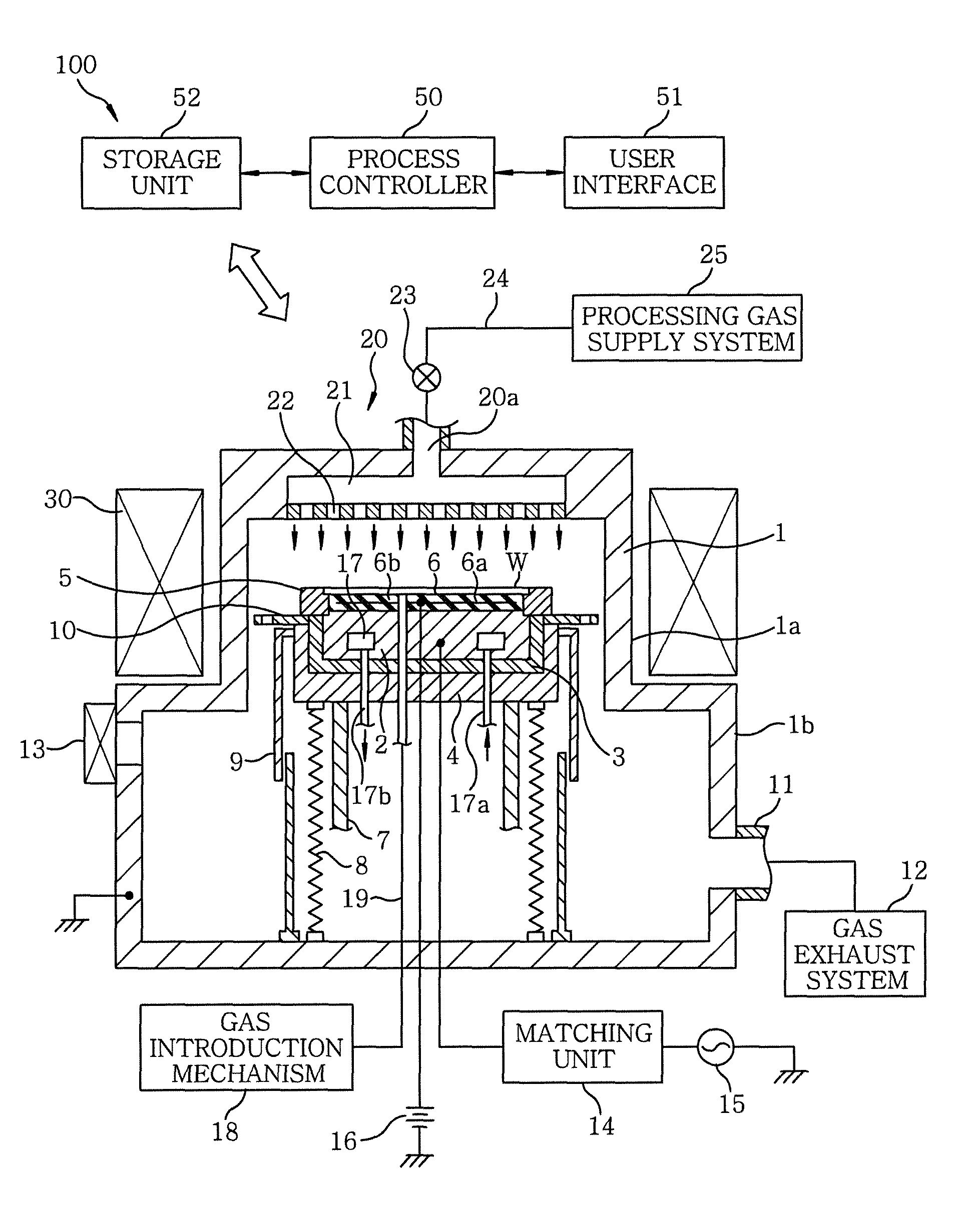
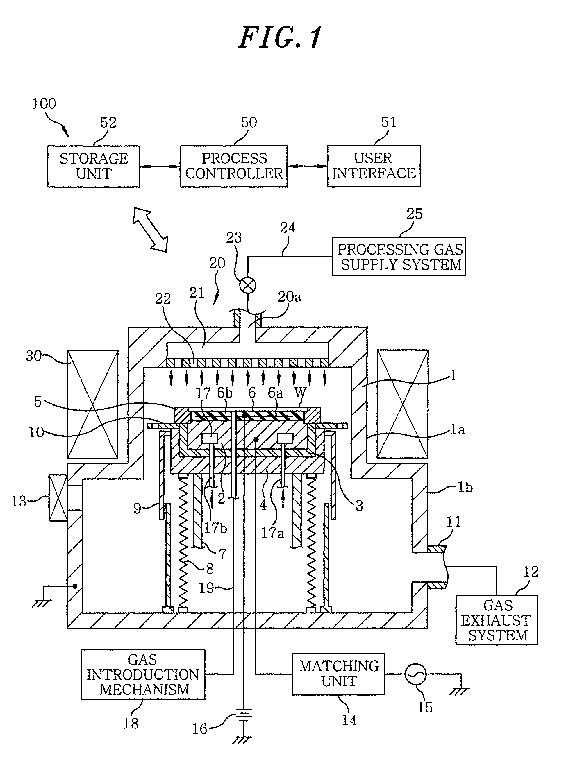
[0082]An etching was performed on the target object 110 of a laminated structure shown in FIG. 5 by using the plasma etching apparatus 100 and a gaseous mixture of CF4 / CHF3 / Ar / O2 as an etching gas, forming the recess 108 by using the resist film (PR) 107 as a mask. Herein, the resist film (PR) 107 was of a film thickness of 400 nm and was formed of a material including elements: C, H, F and O. The anti-reflection film (BARC) 106 was of a film thickness of 58 nm, the silicon nitride film (Si3N4 film) 105 was of a film thickness of 60 nm, and the polycrystalline silicon layer 104 was of a film thickness of 65 nm. Further, the line-and-space pattern of the resist film (PR) 107 was of a line width of 0.6 μm and a space width of 0.24 μm.
[0083]Etching conditions are described as follows:
[0084]CF4 / CHF3 / Ar / O2=20 / 25 / 300 / 10 mL / min (sccm)
[0085]Pressure=13.3 Pa (100 mTorr)
[0086]RF frequency (the high frequency power supply 15)=13.56 MHz
[0087]RF power=400 W (1.27 W / cm2)
[0088]Backside pressure (c...
PUM
| Property | Measurement | Unit |
|---|---|---|
| flow rate | aaaaa | aaaaa |
| flow rate | aaaaa | aaaaa |
| pressure | aaaaa | aaaaa |
Abstract
Description
Claims
Application Information
 - R&D
- Intellectual Property
- Life Sciences
- Materials
- Tech Scout
- Unparalleled Data Quality
- Higher Quality Content
- 60% Fewer Hallucinations
Browse by: Latest US Patents, China's latest patents, Technical Efficacy Thesaurus, Application Domain, Technology Topic, Popular Technical Reports.
© 2025 PatSnap. All rights reserved.Legal|Privacy policy|Modern Slavery Act Transparency Statement|Sitemap|About US| Contact US: help@patsnap.com


