Display Device and Electronic Device
- Summary
- Abstract
- Description
- Claims
- Application Information
AI Technical Summary
Benefits of technology
Problems solved by technology
Method used
Image
Examples
embodiment 1
[0055]In this embodiment, a driving method of an electronic device of one embodiment of the present invention will be described.
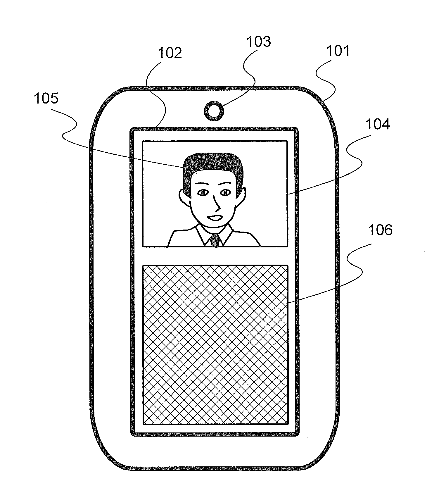
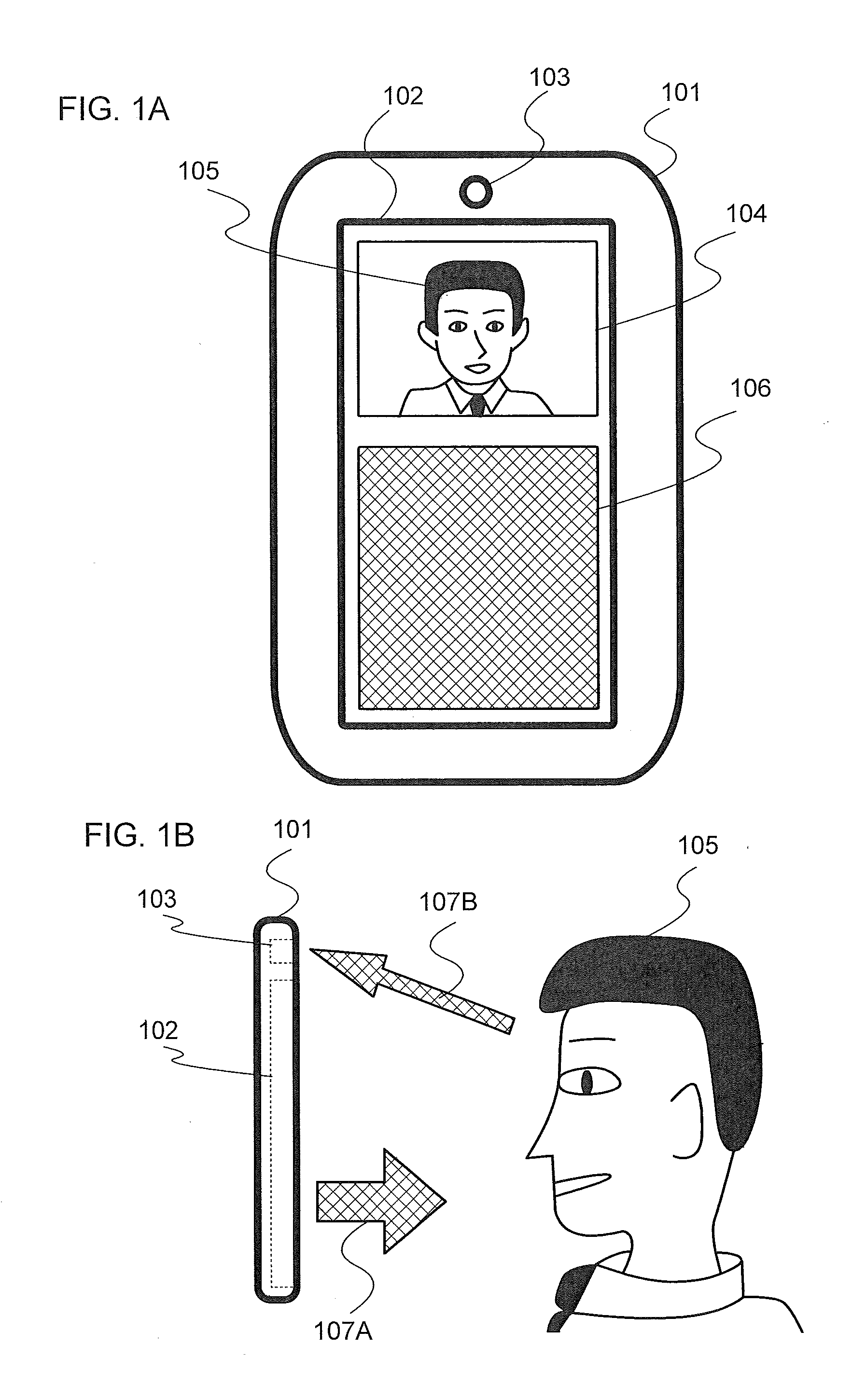
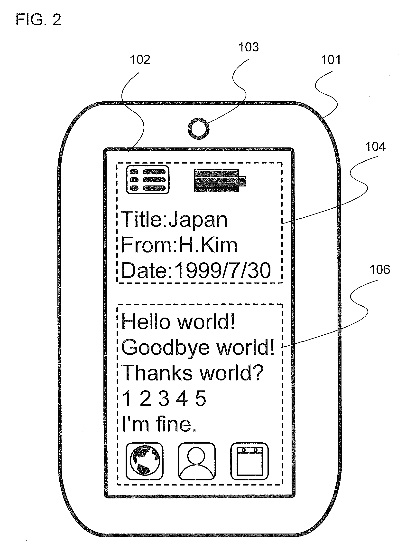
[0056]As illustrated in FIG. 1A, a first surface (e.g., the front surface) of an electronic device 101 is provided with a display device 102 and a camera portion 103, for example.
[0057]The display device 102 has a function of performing a variety of displays. Alternatively, the display device has a function of outputting light to the outside. Note that the display device can also be referred to as a display portion or a display panel.
[0058]The camera portion 103 includes, for example, a lens and an imaging element such as an image sensor and has a function of acquiring an image such as a moving image or a still image. Note that the camera portion can also be referred to as an imaging device.
[0059]First, a first mode will be described. This corresponds to the case of performing a normal operation. Thus, the first mode can also be referred to as a first opera...
embodiment 2
[0104]In this embodiment, a structure of an electronic device of one embodiment of the present invention will be described.
[0105]First, FIG. 21 shows a rough structural diagram of the inside of the electronic device 101.
[0106]A CPU 201 can conduct a variety of calculations and processings and controls a variety of portions.
[0107]The storage device 203 stores at least one of various data, programs, and application software. For example, the storage device 203 can deal with nonvolatile storage media such as flash memory, magnetic disks, CDROM, DVD, and magneto-optical disks. Application software (program) having such a function as is described in Embodiment 1 may be stored in the storage device 203 or a storage medium used therein.
[0108]The storage device 205 stores at least one of various data, programs, and application software. For example, the storage device 203 is a volatile storage device such as DRAM. The CPU 201 can conduct a variety of processings with the use of data or a pr...
embodiment 3
[0120]In this embodiment, another structure of an electronic device of one embodiment of the present invention will be described.
[0121]As illustrated in FIG. 23A, an electronic device 101A includes, for example, a display device 102A and a display device 102B. The region 106 is divided into two regions of a region 106A and a region 106B, for example, and the display device 102A and the display device 102B are provided with the region 106A and the region 106B, respectively.
[0122]Although in FIG. 23A, the display device 102A and the display device 102B are provided with the region 106A and the region 106B, respectively, one embodiment of the present invention is not limited to this example. For example, only one of the display device 102A and the display device 102B may be provided with the region 106.
[0123]FIG. 23B is a side view. The electronic device 101A can be folded in half, for example. There are illuminating light 107C emitted from the region 106A of the display device 102A an...
PUM
 Abstract
Description
Claims
Application Information
 - R&D
- Intellectual Property
- Life Sciences
- Materials
- Tech Scout
- Unparalleled Data Quality
- Higher Quality Content
- 60% Fewer Hallucinations
Browse by: Latest US Patents, China's latest patents, Technical Efficacy Thesaurus, Application Domain, Technology Topic, Popular Technical Reports.
© 2025 PatSnap. All rights reserved.Legal|Privacy policy|Modern Slavery Act Transparency Statement|Sitemap|About US| Contact US: help@patsnap.com


