
Auxiliary drive wheel-side differential unit for four-wheel drive vehicle

Active Publication Date: 2015-06-18
JTEKT CORP
View PDF2 Cites 15 Cited by
  • Summary
  • Abstract
  • Description
  • Claims
  • Application Information

AI Technical Summary

Benefits of technology

The invention provides an auxiliary drive wheel-side differential unit for a four-wheel drive vehicle that prevents a fully differential state of a differential gear unit in a disconnect mode. This is achieved by using an intermeshing disconnect mechanism between the ring gear and the cylrical shaft of the differential case of the differential gear unit. The actuator used to move the movable meshing member includes a spring, first piston, second piston, holder, and trip mechanism. The synchronizer includes a gear-side friction engagement member and a movable-side friction engagement member that synchronize rotation of the movable meshing member with rotation of the ring gear. The technical effects of this invention include preventing damage to the differential gear unit, reducing the size of the differential unit, and improving the stability and efficiency of the vehicle's power transmission system.

Problems solved by technology

Thus, there is an inconvenience that the differential gear unit that couples the axle, on which the control coupling is provided, is placed in a fully differential state during traveling for a long period of time.
Thus, if such a fully differential state continues, there is a possibility that lubricating oil that lubricates the gears, such as the pair of side gears and a pair of pinions, of the differential gear unit becomes insufficient because of rotation of the ring gear.

Method used


Image

  • Auxiliary drive wheel-side differential unit for four-wheel drive vehicle
  • Auxiliary drive wheel-side differential unit for four-wheel drive vehicle
  • Auxiliary drive wheel-side differential unit for four-wheel drive vehicle

Examples


Embodiment Construction

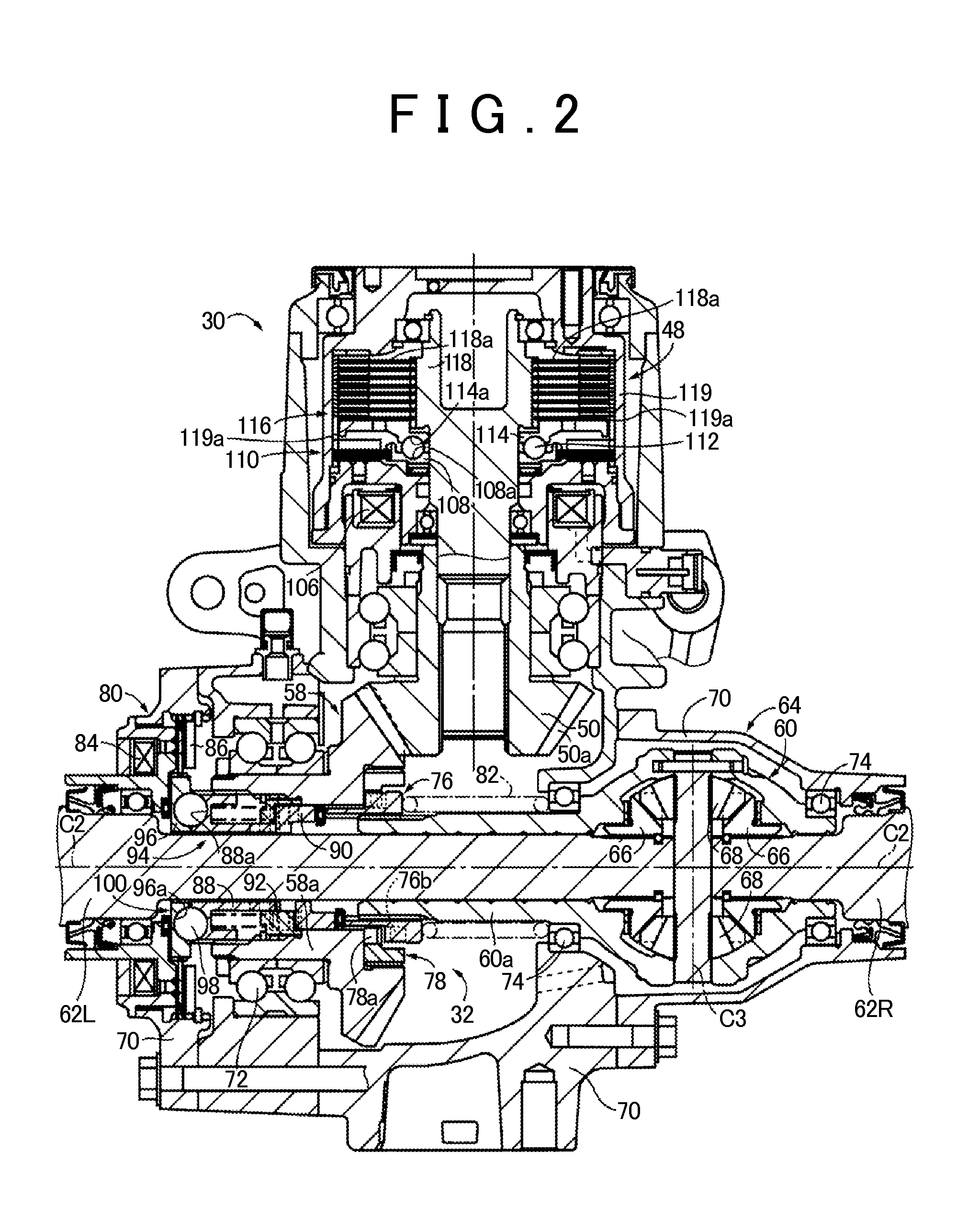
[0022]Hereinafter, embodiments of the invention will be described in detail with reference to the accompanying drawings. In the following embodiment, the drawings are modified or simplified where appropriate, and the scale ratio, shape, and the like, of each portion are not always drawn accurately.

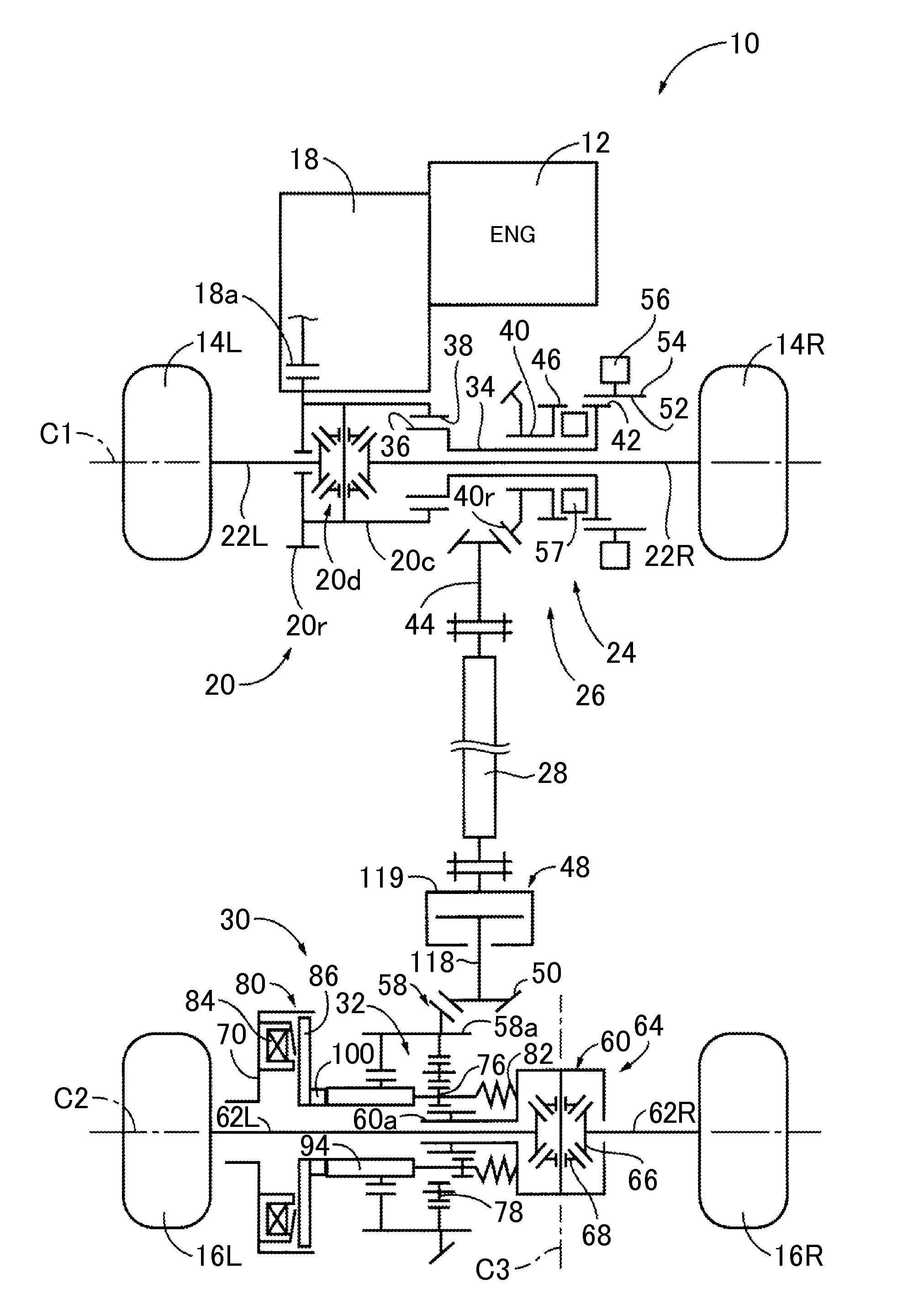
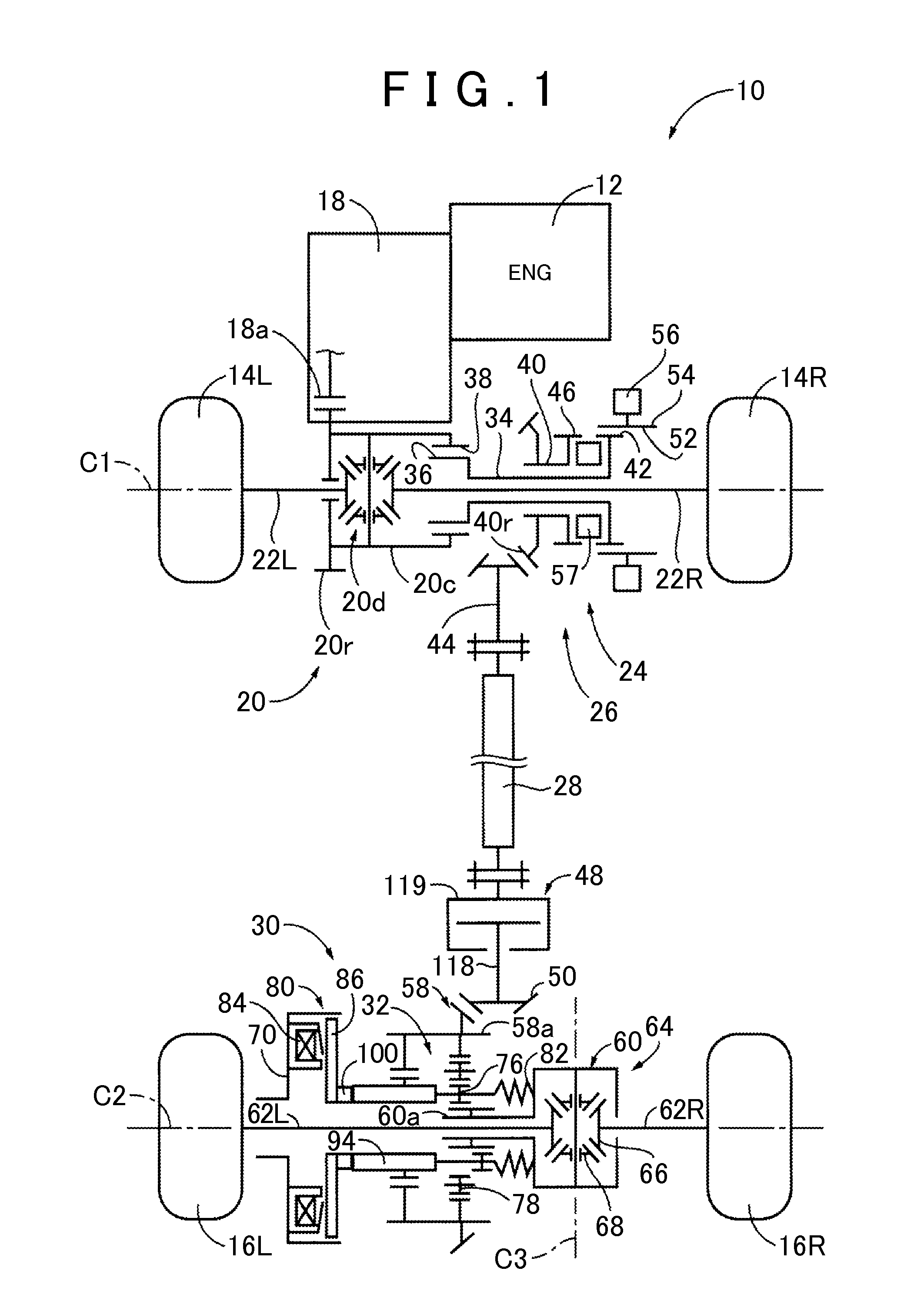
[0023]FIG. 1 is a skeletal view that schematically illustrates the configuration of a four-wheel drive vehicle 10 to which the invention is suitably applied. In FIG. 1, the four-wheel drive vehicle 10 includes an engine 12 as a driving source. The four-wheel drive vehicle 10 includes a four-wheel drive system that includes a first power transmission path and a second power transmission path. The first power transmission path transmits power of the engine 12 to right and left front wheels 14R, 14L (unless specifically distinguished from each other, referred to as front wheels 14) corresponding to main drive wheels. The second power transmission path transmits power of the engine 12 to right...


PUM


Abstract

A movable sleeve of a second clutch is provided between a cylindrical ring gear and a cylindrical shaft of a differential case of a differential gear unit. In a disconnect mode in which a propeller shaft is disconnected from rear wheels, the cylindrical ring gear is disconnected from the differential case by the movable sleeve of the second clutch. Thus, in the disconnect mode, a fully differential state of the differential gear unit is prevented.

Description

INCORPORATION BY REFERENCE[0001]The disclosure of Japanese Patent Application No. 2013-261873 filed on Dec. 18, 2013 including the specification, drawings and abstract is incorporated herein by reference in its entirety.BACKGROUND OF THE INVENTION[0002]1. Field of the Invention[0003]The invention relates to, in an auxiliary drive wheel-side differential unit for a four-wheel drive vehicle that includes a power transmission member configured to transmit driving force from a driving source to auxiliary drive wheels in a four-wheel drive mode and that disconnects the power transmission member from the auxiliary drive wheels in a two-wheel drive mode, a technique for preventing a fully differential state of a differential gear unit provided in the auxiliary drive wheel-side differential unit when the power transmission member is disconnected from the auxiliary drive wheels.[0004]2. Description of Related Art[0005]There is known a four-wheel drive vehicle in which a two-wheel drive mode ...

Claims


Application Information

Patent Timeline
IPC IPC(8): B60K17/35F16D27/09F16H48/08
CPCB60K17/3515F16H2048/085F16D27/09F16H48/08F16D27/118B60K17/3462B60K23/0808F16D2011/004F16D2023/123
Inventor TAMOTO, HIDEKIYOSHIMURA, TAKAHIRO
Owner JTEKT CORP
Learn More