Repair and strengthening system for reinforced concrete structure
- Summary
- Abstract
- Description
- Claims
- Application Information
AI Technical Summary
Benefits of technology
Problems solved by technology
Method used
Image
Examples
embodiment 1
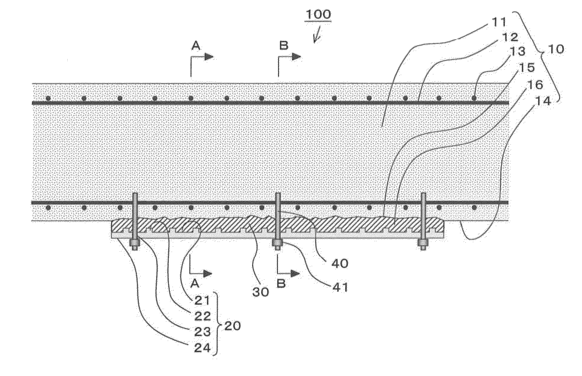
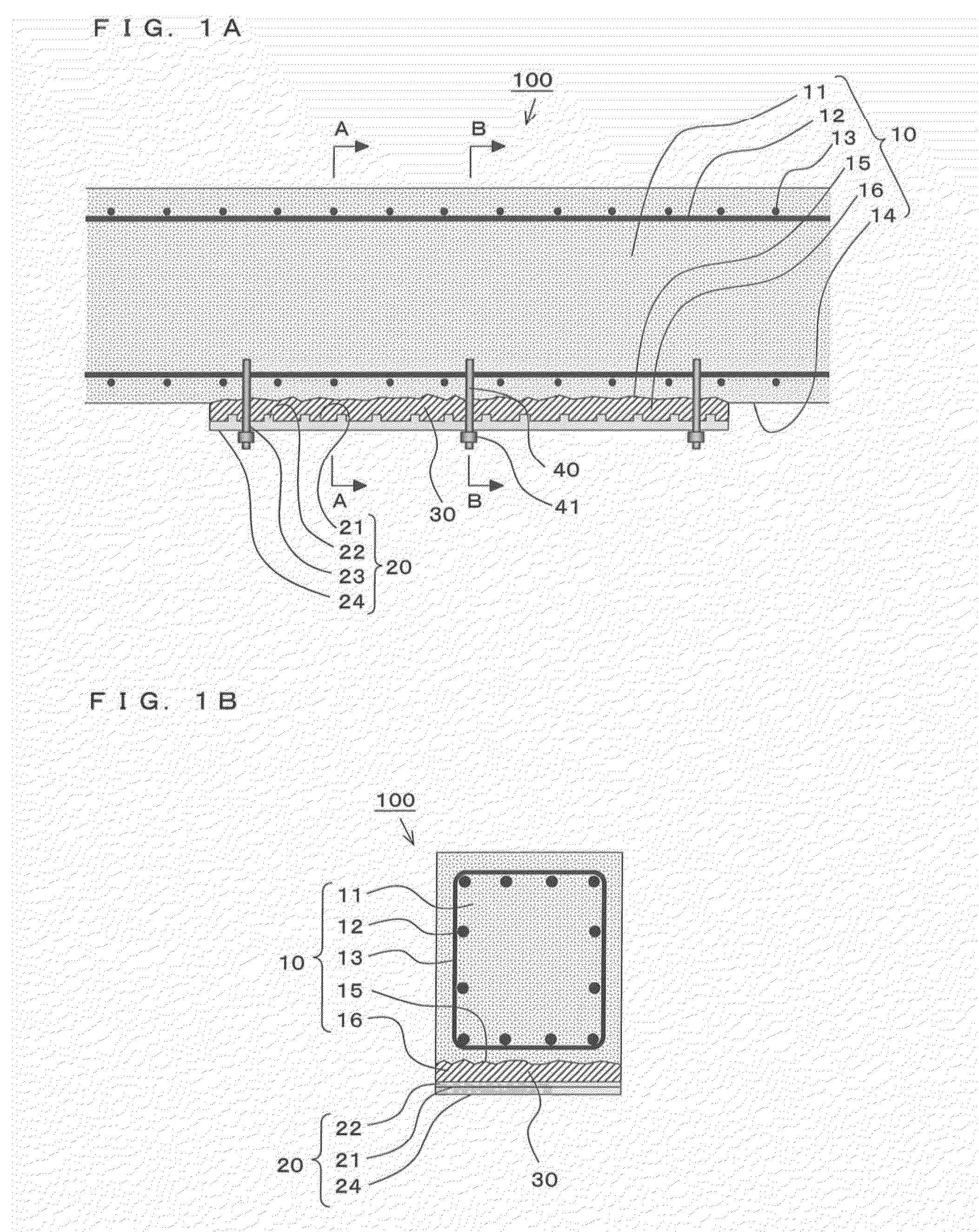
[0083]A repair and strengthening system for a reinforced concrete structure according to Embodiment 1 of the present invention is used to repair or strengthen a reinforced concrete structure. Hereinafter, a strengthening example will be described with reference to FIGS. 1 and 2, and a repair example will be described with reference to FIG. 3.
(Strengthening Example)
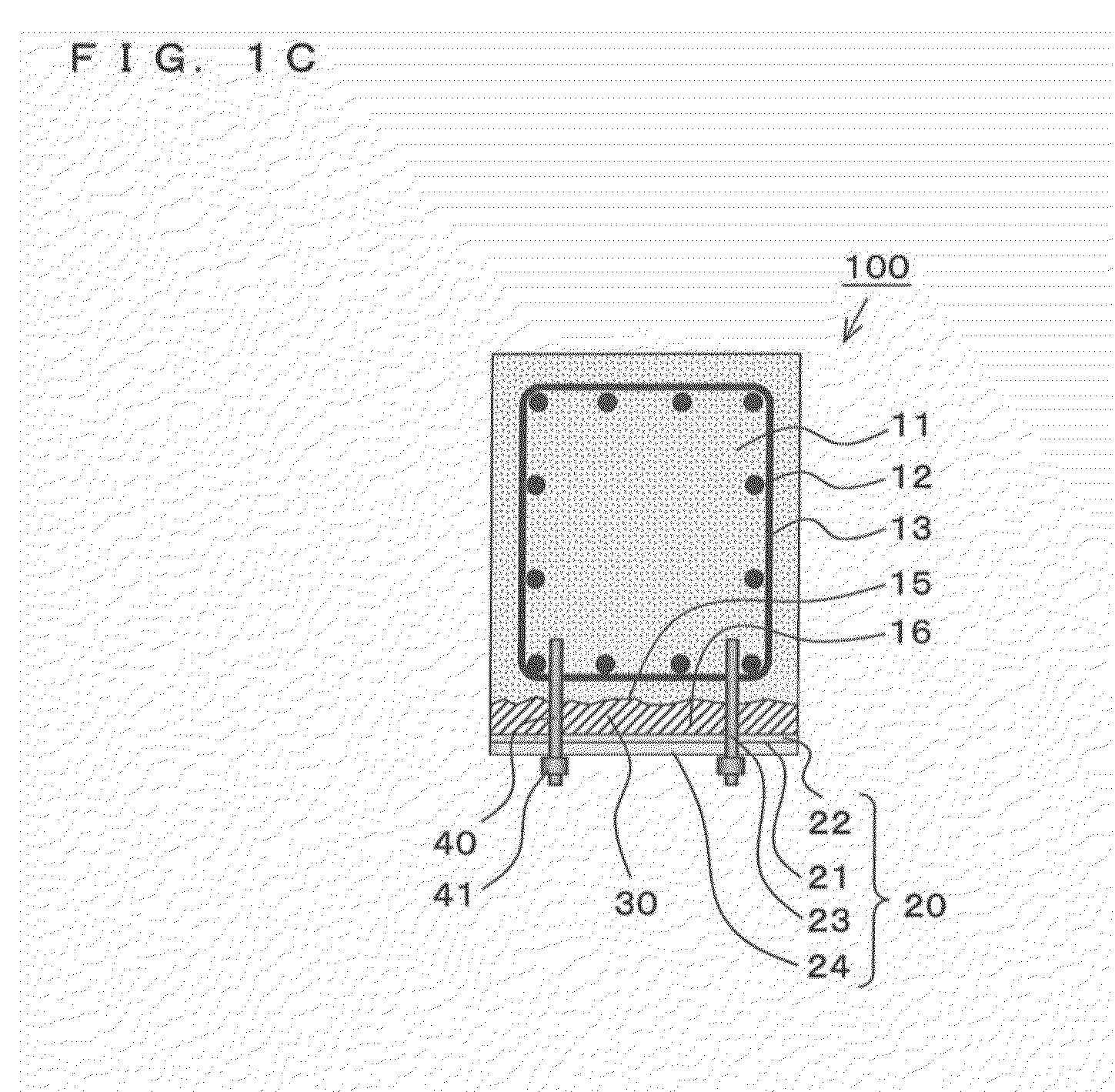
[0084]FIGS. 1 and 2 illustrate a strengthening example for explaining the repair and strengthening system for a reinforced concrete structure according to Embodiment 1 of the present invention. FIG. 1A is a partially see-through front view, FIG. 1B is a sectional side view taken along A-A in FIG. 1A, and FIG. 1C is a sectional side view taken along B-B in FIG. 1A. FIG. 2 is an enlarged front view of a part of a steel plate. These figures are schematic only, and not intended to limit the present invention to the particular forms (such as shapes or quantities) illustrated.
[0085]In FIG. 1, a repair and strengthening system fo...
embodiment 2
[0107]FIG. 4 illustrates a repair example for explaining a repair and strengthening system for a reinforced concrete structure according to Embodiment 2 of the present invention, in which FIG. 4A is a partially see-through front view, FIG. 4B is a sectional side view taken along A-A in FIG. 4A, and FIG. 4C is a sectional side view taken along B-B in FIG. 4A. Portions that are the same as or equivalent to those in Embodiment 1 are denoted by the same reference signs, and a description of these portions is partially omitted. Further, these figures are schematic only, and not intended to limit the present invention to the particular forms (such as shapes or quantities) illustrated.
Repair Example
[0108]In FIG. 4, a repair and strengthening system for a reinforced concrete structure (to be referred to as “repair and strengthening system” hereinafter) 200 uses a steel-plate support member 50 that is square U-shaped, instead of the hang bolt 40 of the repair and strengthening system 100.
[01...
embodiment 3
[0117]FIG. 5 illustrates a repair and strengthening system for a reinforced concrete structure according to Embodiment 3 of the present invention, in which FIG. 5A is a partially enlarged, partially see-through front view, and FIG. 5B is a partially enlarged side sectional view. Portions that are the same as or equivalent to those in Embodiments 1 and 2 are denoted by the same reference signs, and a description of these portions is partially omitted. Further, these figures are schematic only, and not intended to limit the present invention to the particular forms (such as shapes or quantities) illustrated.
[0118]In FIG. 5, a repair and strengthening system for a reinforced concrete structure (to be referred to as “repair and strengthening system” hereinafter) 300 makes it possible to adjust the position of the steel-plate support member 50 in the repair and strengthening system 200 for a reinforced concrete structure. Otherwise, the repair and strengthening system 300 is the same as ...
PUM
 Abstract
Description
Claims
Application Information
 - R&D
- Intellectual Property
- Life Sciences
- Materials
- Tech Scout
- Unparalleled Data Quality
- Higher Quality Content
- 60% Fewer Hallucinations
Browse by: Latest US Patents, China's latest patents, Technical Efficacy Thesaurus, Application Domain, Technology Topic, Popular Technical Reports.
© 2025 PatSnap. All rights reserved.Legal|Privacy policy|Modern Slavery Act Transparency Statement|Sitemap|About US| Contact US: help@patsnap.com


