
Hybrid high-inertia synchronous condenser facility

a synchronous condenser and high-inertia technology, applied in the field of synchronous condensers, can solve the problem of increasing the cost of adding inertia to the power grid

Inactive Publication Date: 2015-06-18
GENERAL ELECTRIC CO
View PDF3 Cites 12 Cited by
  • Summary
  • Abstract
  • Description
  • Claims
  • Application Information

AI Technical Summary

Benefits of technology

The present invention is a hybrid high-inertia synchronous condenser facility and a method for delivering reactive power to an electrical grid. The facility comprises a synchronous condenser, voltage transformer, banks of capacitors and reactors, which are connected to the grid through a controller. The method involves monitoring the electrical grid and the facility, computing the amount of reactive power to be delivered, and controlling the operations of the facility accordingly. This invention overcomes the deficiencies of conventional modeling methods and allows for more efficient and effective delivery of reactive power.

Problems solved by technology

When a large amount of inertia is desired for a grid, multiple synchronous condensers are used or larger condensers are used, and this increases the cost for adding the inertia to the power grid.

Method used


Image

  • Hybrid high-inertia synchronous condenser facility
  • Hybrid high-inertia synchronous condenser facility
  • Hybrid high-inertia synchronous condenser facility

Examples


Embodiment Construction

[0007]Embodiments of the present invention overcome the aforementioned deficiencies noted in the conventional modeling methods.

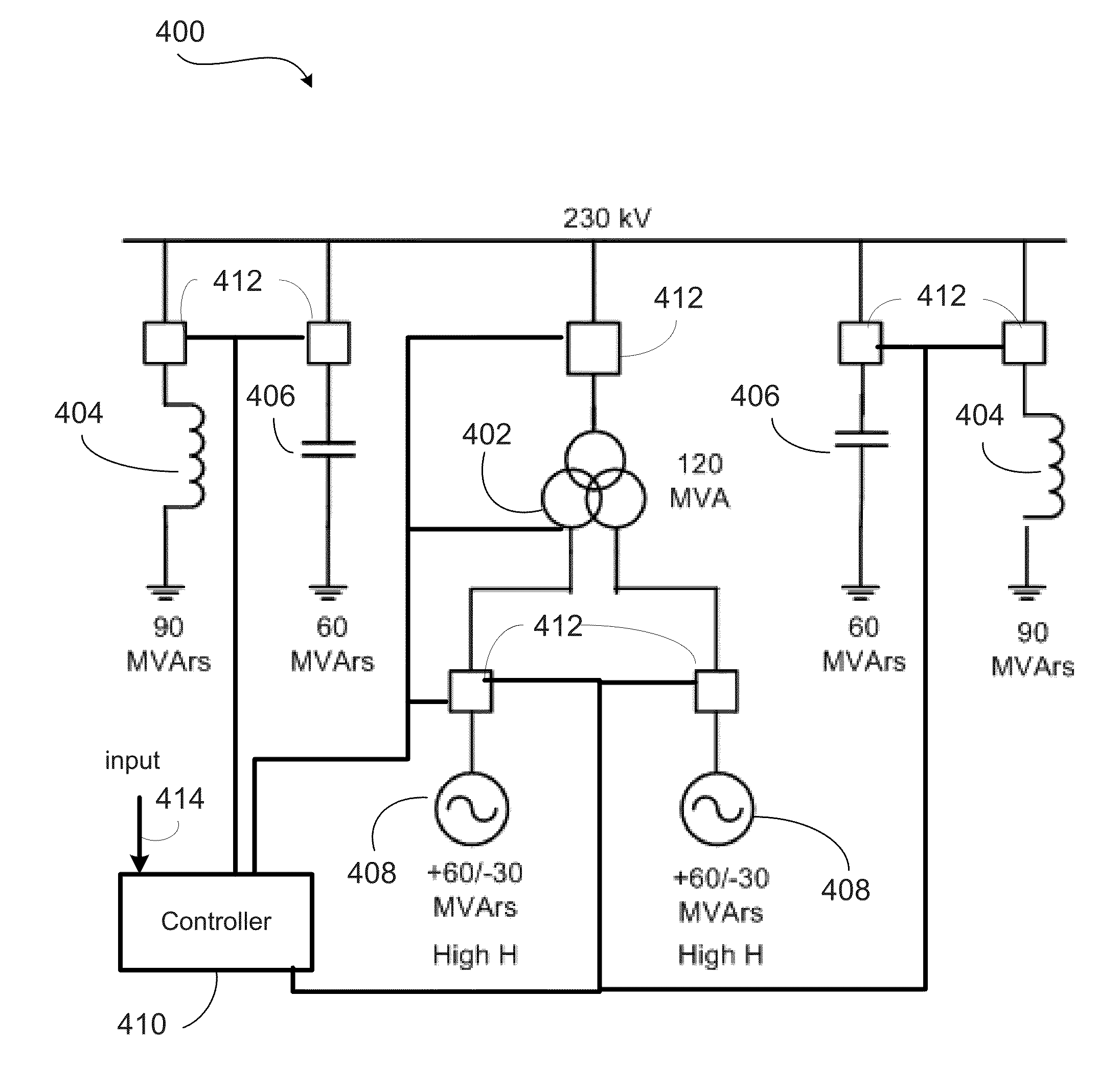
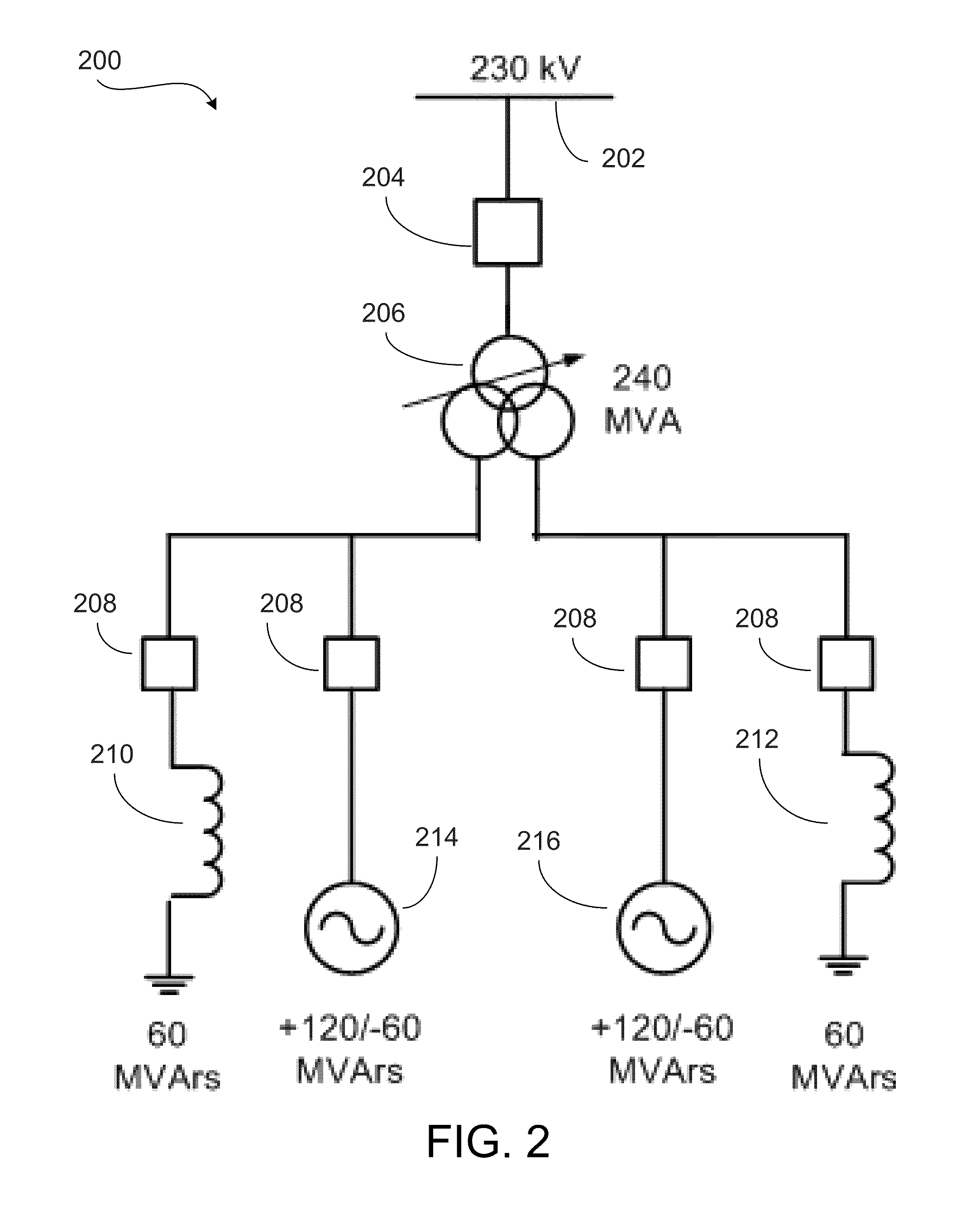
[0008]In one embodiment, a hybrid high-inertia synchronous condenser facility is provided. The hybrid high-inertia synchronous condenser facility comprises at least one synchronous condenser, a voltage transformer connecting the at least one synchronous condenser to an electrical grid, at least one bank of capacitors switchably connected to the electrical grid, at least one bank of reactors switchably connected to the electrical grid, and a controller for controlling connection of the voltage transformer, the at least one bank of shunt capacitors, and the at least one bank of shunt reactors to the electrical grid.

[0009]In another embodiment, a method for delivering reactive power from a hybrid high inertia synchronous condenser facility to an electrical grid is provided. The method comprises monitoring the electrical grid, monitoring the hybrid high inertia ...


PUM


Abstract

A hybrid high inertia synchronous condenser facility for delivering reactive power to an electrical grid comprises at least one synchronous condenser, a voltage transformer connecting the at least one synchronous condenser to an electrical grid, at least one bank of capacitors switchably connected to the electrical grid, at least one bank of reactors switchably connected to the electrical grid, and a controller for controlling connection of the voltage transformer, the at least one bank of shunt capacitors, and the at least one bank of shunt reactors to the electrical grid. The synchronous condenser is equipped with a flywheel.

Description

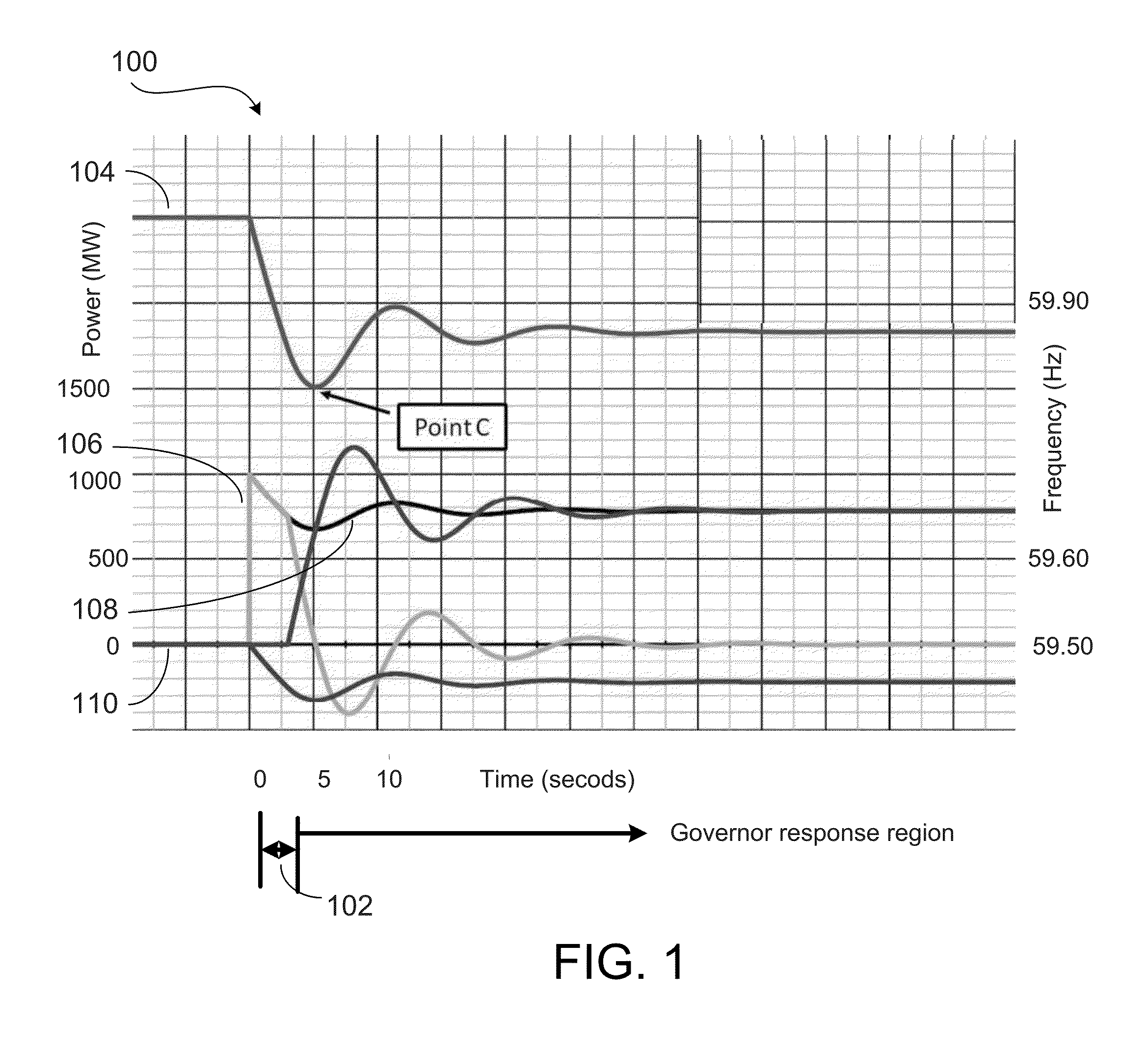
FIELD OF THE INVENTION[0001]The present invention generally relates to synchronous condenser, and more specifically to high-inertia synchronous condenser.BACKGROUND OF THE INVENTION[0002]The frequency response of power systems is decreasing due to the displacement of conventional power plants with alternate power sources such as wind plants (without inertia option) and solar plants. In addition, motor loads are increasingly connected to variable speed drives that de-couple the machine from the grid.[0003]As conventional power plants are replaced by alternative power sources, such as wind plants and solar plants, and as more and more synchronous and induction motors are connected to the grid via motor drives, the inertia associated with these conventional power plants and motors are also removed from the electric power grid. The inertia is an energy stored as rotating energy in machines on a system. One way to restore the inertia to the grid is through use of synchronous condensers. ...

Claims


Application Information

Patent Timeline
Patent Type & Authority Applications(United States)
IPC IPC(8): G05F1/70
CPCG05F1/70H02J3/1828H02J3/1878H02J3/1885Y04S10/22Y02E40/30Y02E40/70H02J13/00032H02J13/00002Y04S10/30Y02E60/00
Inventor SKLIUTAS, JOHN PAULSCHARTNER, CHRIS OWENSHAO, MIAOLEI
Owner GENERAL ELECTRIC CO
Learn More