Fingerprint sensing system and method

a fingerprint and sensing technology, applied in the field of fingerprint sensing systems, can solve the problems of pixel signal value not being correctly reflected, requiring a relatively large capacitance, and wet fingers and/or external interference, etc., to achieve the effect of improving fingerprint sensing and improving fingerprint sensing

Active Publication Date: 2015-06-18
FINGERPRINT CARDS ANACATUM IP AB
View PDF4 Cites 33 Cited by
  • Summary
  • Abstract
  • Description
  • Claims
  • Application Information

AI Technical Summary

Benefits of technology

[0010]In view of above-mentioned and other drawbacks of the prior art, it is an object of the present invention to provide an improved fingerprint sensing system, in particular providing for improved sensing of fingerprints from “difficult” fingers, such as dry fingers. Additionally, the present inventors have found that interfere

Problems solved by technology

This, however, requires a relatively large capacitance.
Additionally, the present inventors have found that interference, such as high frequency components of common mode noise originating from switched power supply devices, may influence the fingerprint sensing performance of a fingerprint sensing system.
Such difficult measurement conditions may, for example, result from particularly dry/wet fingers and/

Method used


Image

  • Fingerprint sensing system and method
  • Fingerprint sensing system and method
  • Fingerprint sensing system and method

Examples


first embodiment

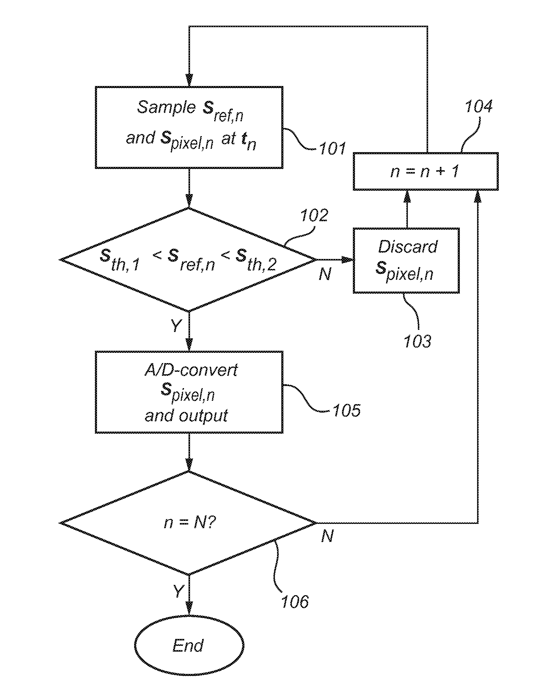
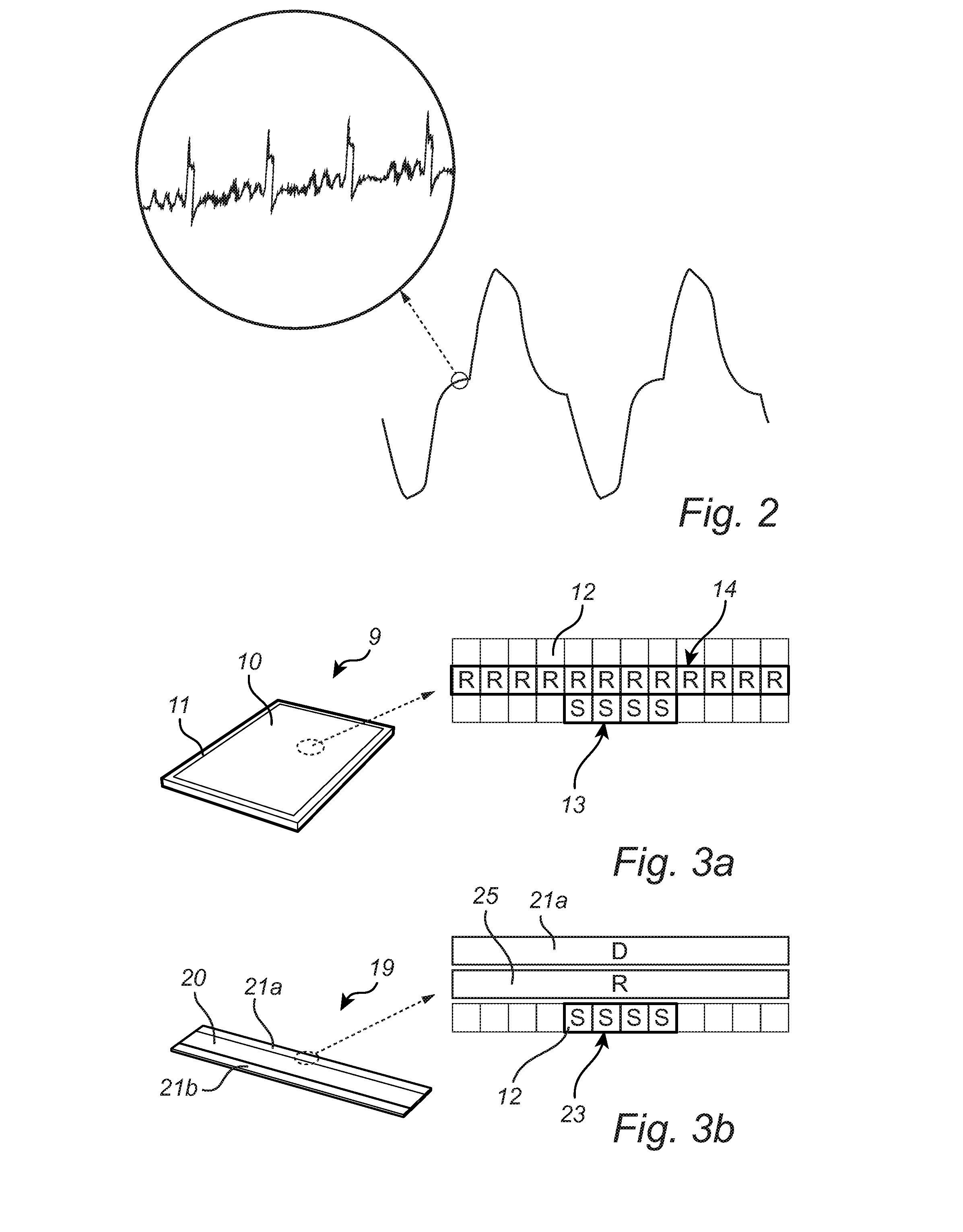
[0089]the method according to the present invention will now be described with reference to the flow-cart in FIG. 5 and the representative diagrams in FIGS. 6a-c. In a first step 101, the reference signal Sref and the pixel signal Spixel are sampled to provide the n:th sample Sref,n of the reference signal (the reference signal value) and the n:th sample Spixel,n of the pixel signal (the pixel signal value) at the n:th sampling time tn. The respective samples may advantageously be acquired using so-called correlated double sampling, which may be used to remove any effects of the low frequency component of the common-mode noise (see FIG. 2). Correlated double sampling is, per se, well known to the skilled person, and correlated double sampling from sensing elements of a capacitive fingerprint sensor is described in detail in the above-mentioned document U.S. Pat. No. 7,864,992.

[0090]Referring now to FIGS. 6a-c, an exemplary sampling as carried out in the first step 101 will be descri...

second embodiment

[0099]the method according to the present invention will now be described with reference to the flow-cart in FIG. 7.

[0100]This second embodiment of the method according to the invention mainly differs from the above-described first embodiment in that a post-processing of the pixel signal values Spixel,n is carried out based on corresponding reference signal values Sref,n.

[0101]Accordingly, in a first step 201, a series of reference signal values Sref,n and a corresponding series of pixel signal values Spixel,n are sampled at sampling times t1−tN. The sampling of each reference signal value / pixel signal value may be carried out as described above with reference to FIG. 5 and FIGS. 6a-c.

[0102]In the next step 202, a series of modified pixel signal values is determined based on the series of pixel signal values Spixel,n and the corresponding series of reference signal values Sref,n.

[0103]Due to the averaging obtained using the reference sensing structure (14 in FIGS. 3a and 25 in FIG....

third embodiment

[0104]Finally, the method according to the present invention will now be described with reference to the flow-chart in FIG. 8 and the representative diagrams in FIGS. 9a-c.

[0105]The flow-chart in FIG. 8 concerns the acquisition of a single pixel signal value (or the simultaneous acquisition of pixel signals from several sensing elements).

[0106]In a first step 301, the pixel signal Spixel is sampled at a first sampling time tn,0 resulting in a first sample Spixel,n,0. Subsequently, in step 302, the pixel signal is sampled at a second sampling time tn,1 resulting in a second sample Spixel,n,1. Rather than there being a fixed time difference between the first sampling time and the second sampling time, the second sampling time is dependent on the value of the reference signal Sref.

[0107]Specifically, the reference signal Sref is compared with a threshold value Sref,th, and when the reference signal reaches the threshold value, the second sample of the pixel signal is taken.

[0108]This ...


PUM


Abstract

The present invention relates to a method of determining a representation of a fingerprint pattern. The method comprises the steps of acquiring a reference signal indicative of an electric coupling between a hand surface having friction ridges and a reference sensing structure extending across a plurality of the friction ridges; and determining the representation of the fingerprint pattern based on the reference signal and a capacitive coupling between the finger and each of a plurality of sensing elements. The acquired reference signal can, for example, be used for controlling the sensing elements so that the sensing performed by the sensing elements is carried out using favorable timing, when the signal quality is good. Alternatively, or in combination, the acquired reference signal may be used for post-processing, whereby the signals/signal values obtained by the sensing elements are modified depending on the corresponding values of the reference signal.

Description

CROSS-REFERENCE TO RELATED APPLICATIONS[0001]This application claims the benefit of Swedish Patent Application No. 1351489-8, filed Dec. 12, 2013. The disclosure of the above application is incorporated herein by reference in its entirety.FIELD OF THE INVENTION[0002]The present invention relates to a fingerprint sensing system and to a method of determining a representation of a fingerprint pattern.BACKGROUND OF THE INVENTION[0003]Various types of biometric systems are used more and more in order to provide for increased security and / or enhanced user convenience.[0004]In particular, fingerprint sensing systems have been adopted in, for example, consumer electronic devices, thanks to their small form factor, high performance and user acceptance.[0005]Among the various available fingerprint sensing principles (such as capacitive, optical, thermal etc.), capacitive sensing is most commonly used, in particular in applications where size and power consumption are important issues.[0006]A...

Claims


Application Information

Patent Timeline
IPC IPC(8): G06K9/00G06V10/75G06V40/13
CPCG06K9/00013G06V40/1306G06V40/1376G06V10/751
Inventor RIEDIJK, FRANK ROBERTTHORNBLOM, HANS
Owner FINGERPRINT CARDS ANACATUM IP AB
Why Eureka
Try Eureka