Image forming apparatus, image diagnostic method, and image diagnostic system
a technology of image diagnostics and forming apparatuses, applied in the field of image forming apparatuses, can solve the problems of reducing affecting the accuracy of image diagnostics, so as to reduce the amount of image data and reduce the difficulty of image diagnostics.
- Summary
- Abstract
- Description
- Claims
- Application Information
AI Technical Summary
Benefits of technology
Problems solved by technology
Method used
Image

Examples
embodiment 1
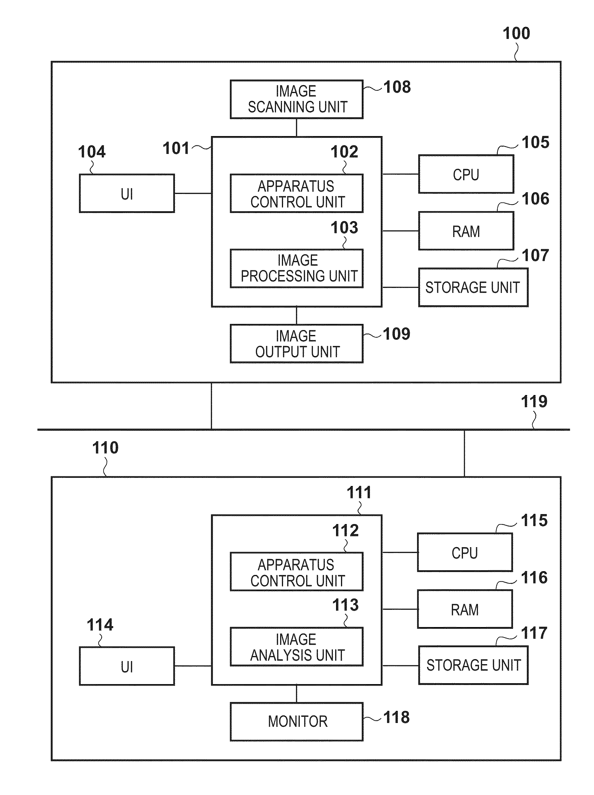
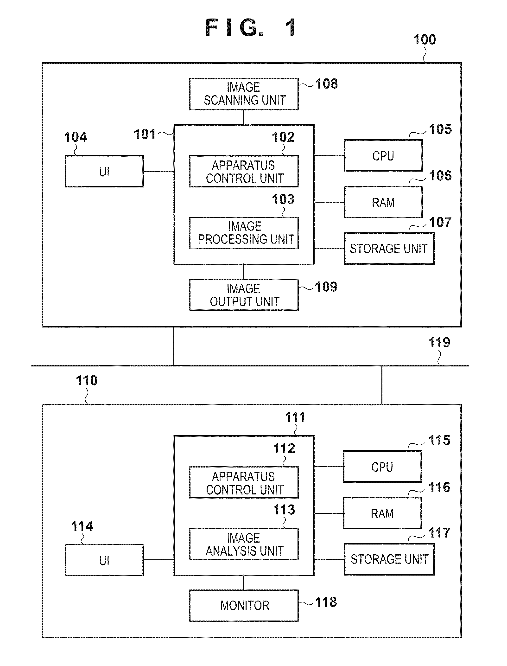
Configuration of Remote Analysis System
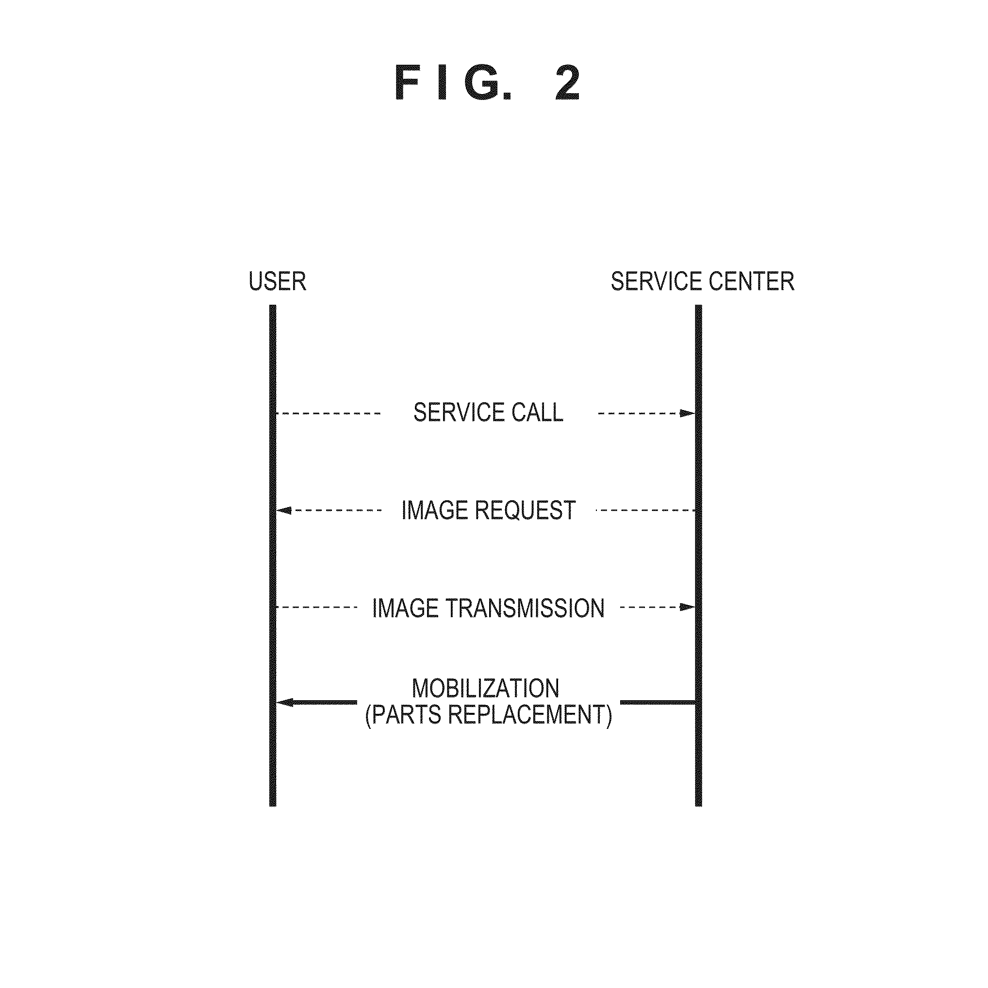
[0019]Hereinafter, embodiments for implementing the present invention will be described with reference to the drawings. FIG. 2 shows procedures of image diagnostics according to this embodiment. When a problem occurs, a user makes a service call to a service center. The service center deals with the problem by telephone, and requests the user to output an image diagnostic chart and to provide a scanned image of the output chart. The user outputs the chart according to the instruction of the service center, and transmits the scanned image to the service center. The service center analyzes the image transmitted by the user using the image diagnostic system to find the cause of the image quality problem of the user. Based on the analysis results, a service person carrying replacement parts is mobilized to the user's location. With this procedure, a diagnosis is made using the test chart, and the cause of the problem in the apparatus is specified.
[...
embodiment 2
[0039]Only parts that differ from Embodiment 1 described above will be described herein. Unlike Embodiment 1, this embodiment proposes a method of further reducing the size of image data to be transmitted by the image forming apparatus 100, based on the analysis data accumulated in the image diagnostic apparatus 110.
[0040]In an image diagnostic system, as image quality problems of the user are analyzed, the analysis results are accumulated. That is, it is thought that a trend regarding image quality problems with a high occurrence frequency will appear. Examples thereof include a trend unique to the machine of the user which appears due to the installation environment and use frequency of the image forming apparatus 100, and a trend that appears due to the difference in parts or mechanical configuration for each machine type. In Embodiment 1, scanned images of the analysis charts corresponding to every analysis technique are transmitted to the image diagnostic apparatus 110, but wit...
embodiment 3
[0045]Only parts that differ from Embodiment 2 described above will be described herein. Unlike Embodiment 2, this embodiment proposes a method of more reliably associating the scanning order of the analysis charts and the transmission settings. In the case where scanned images are edited based on the premise that the analysis charts are scanned in the same order as the order in which they are output, it is thought that if the order goes wrong, the transmission settings of all the scanned images will go wrong and the analysis will no longer be possible, unless the identification information is printed in a superimposed manner.
[0046]Examples of a method of identifying an analysis chart include a method in which chart information is somehow embedded, for example, using a technique such as a QR code (registered trademark) when outputting the analysis chart, and the chart information is analyzed after scanning. However, in the case of using a QR code, the image forming apparatus 100 is ...
PUM
 Abstract
Description
Claims
Application Information
 - R&D
- Intellectual Property
- Life Sciences
- Materials
- Tech Scout
- Unparalleled Data Quality
- Higher Quality Content
- 60% Fewer Hallucinations
Browse by: Latest US Patents, China's latest patents, Technical Efficacy Thesaurus, Application Domain, Technology Topic, Popular Technical Reports.
© 2025 PatSnap. All rights reserved.Legal|Privacy policy|Modern Slavery Act Transparency Statement|Sitemap|About US| Contact US: help@patsnap.com