Focus detection apparatus and focus detection method

a technology of focus detection and focus detection, which is applied in the direction of camera focusing arrangement, printers, instruments, etc., can solve the problems the inability to control the focus detection for a significantly defocused image, and achieve the effect of reducing the accuracy of focus detection

Inactive Publication Date: 2015-03-03
CANON KK
View PDF6 Cites 0 Cited by
  • Summary
  • Abstract
  • Description
  • Claims
  • Application Information

AI Technical Summary

Benefits of technology

[0007]The present invention has been made in consideration of the above situation, and allows a reduction in the accuracy of focus detection to be avoided in a focus detection apparatus that has the function of dividing a line sensor into a plurality of blocks and controlling charge accumulation for each block.

Problems solved by technology

The shorter range of field may result in the inability to capture the contrast of an object sufficiently, thus leading to a problem of reduction in focus detection accuracy.
In addition, the shorter range of field limits the detectable defocus range, thus causing the problem of inability to control focus detection for a significantly defocused image of an object.

Method used


Image

  • Focus detection apparatus and focus detection method
  • Focus detection apparatus and focus detection method
  • Focus detection apparatus and focus detection method

Examples


first embodiment

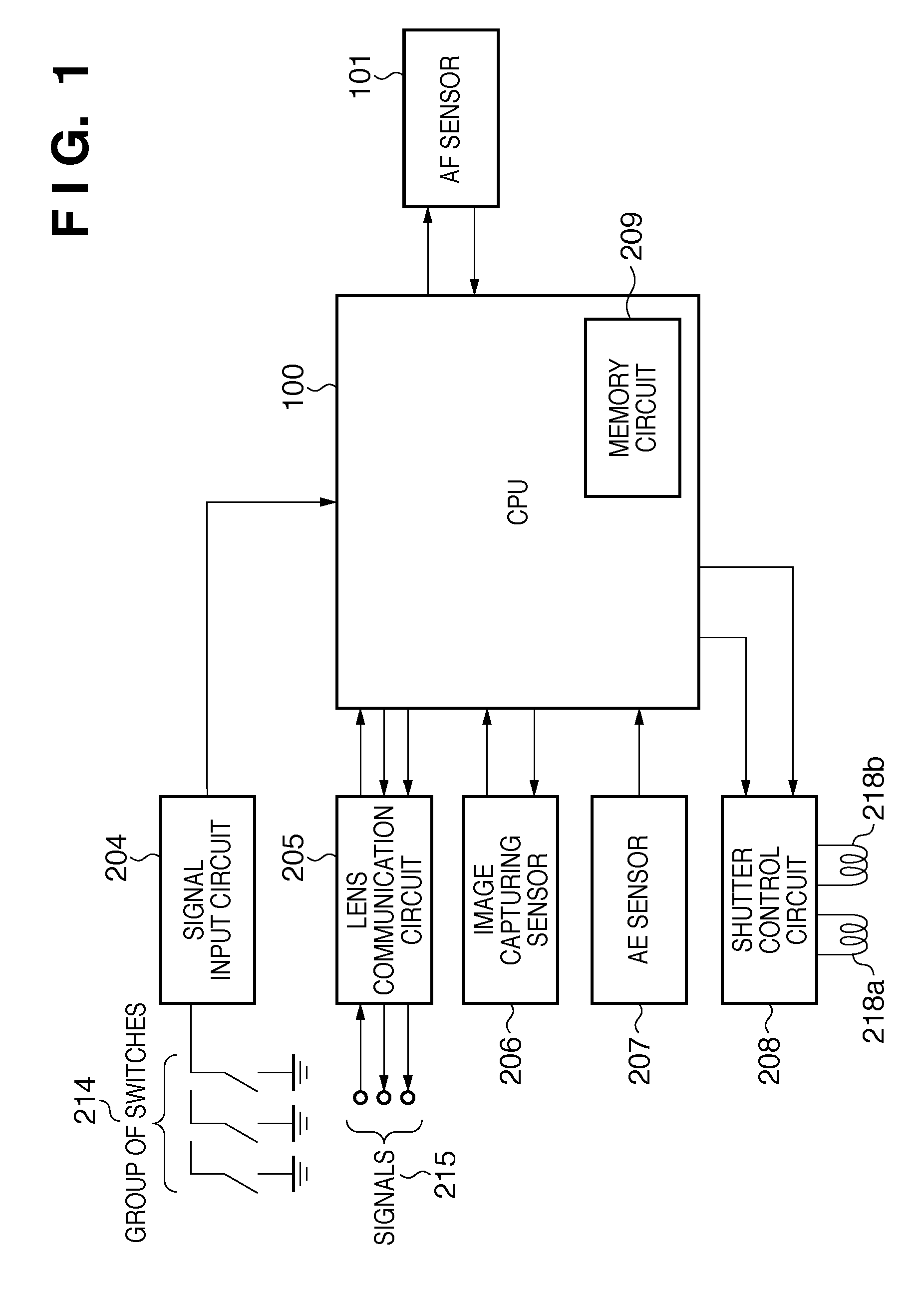
[0025]FIG. 1 is a block diagram illustrating the configuration of a camera body according to a first embodiment of the present invention, and in the first embodiment, the camera body is intended for use with a removable imaging lens (not shown) attached. As a matter of course, the present invention is not to be considered limited to this camera, it comes near to stating the obvious that the present invention may be directed to a camera integrated with an imaging lens.

[0026]In FIG. 1, reference numeral 100 denotes a microcomputer (hereinafter, referred to as a “CPU”) for a camera. The CPU 100 has a memory circuit 209 built-in, such as a ROM storing a program for controlling the camera operation, a RAM for storing variants, and an EEPROM (electrically erasable programmable read-only memory) for storing various types of parameters.

[0027]To the CPU 100, a signal input circuit 204, a lens communication circuit 205, an image capturing sensor 206, an AE sensor 207, a shutter control circui...

second embodiment

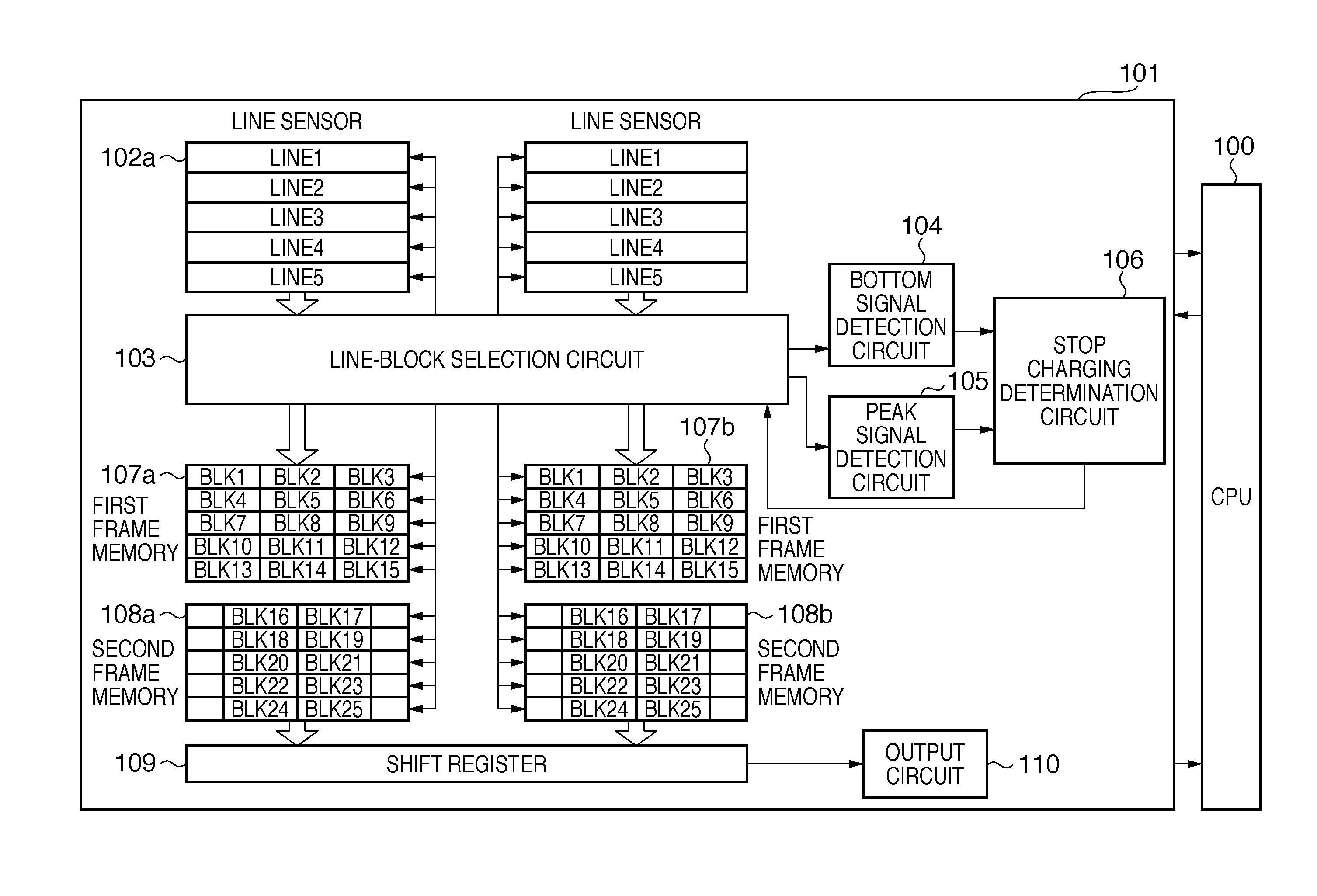
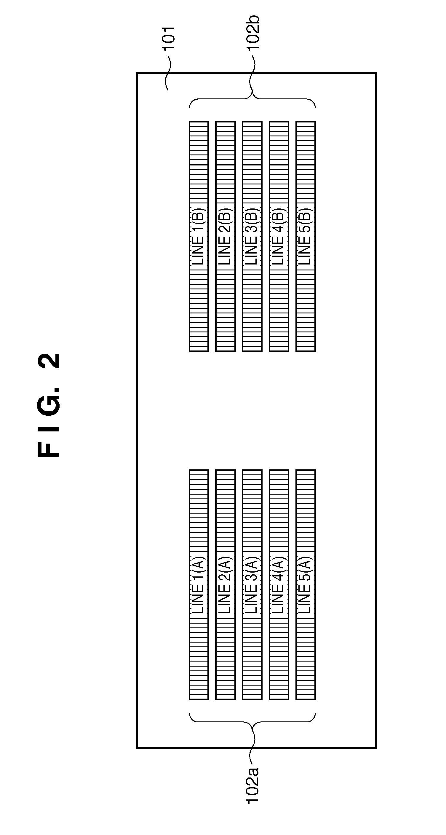
[0060]Next, a second embodiment of the present invention will be described. The AF sensor 101 in the first embodiment described above divides the groups of line sensors 102a and 102b in accordance with the first divisional pattern shown in FIG. 4A and the second divisional pattern shown in FIG. 4B. In the second embodiment, another example of divisional patterns will be described which are different from the first and second divisional patterns.

[0061]FIGS. 7A and 7B show divisional patterns in the second embodiment. FIG. 7A shows a third divisional pattern, in which each line sensor is divided into three, and only pixel signals from two blocks at either end are used for focus detection processing. In addition, FIG. 7B shows a fourth divisional pattern, in which each line sensor is divided into three, and only pixel signals from one central block are used for focus detection processing. It is to be noted that the third divisional pattern and the fourth divisional pattern have differe...


PUM


Abstract

A focus detection apparatus comprises: a photoelectric converter including a pair of line sensors to output electrical signals; a selection unit constructed to select one of focus detection points; a control unit constructed to divide the pair of line sensors into a plurality of pairs of blocks in accordance with different divisional patterns which make the resultant plurality of pairs of blocks respectively corresponding to the focus detection points, and read out electrical signals from each pair of blocks when the levels of the electrical signals of the pair of blocks reach a level suitable for focus detection; frame memories, constructed to store the read out electrical signals, corresponding to the divisional patterns; and a focus detection unit constructed to detect a focus state of an imaging lens, on the basis of a phase difference between electrical signals of the pair of blocks corresponding to the selected focus detection point.

Description

BACKGROUND OF THE INVENTION[0001]1. Field of the Invention[0002]The present invention relates to a focus detection apparatus and focus detection method for use in an image capturing apparatus such as a camera.[0003]2. Description of the Related Art[0004]Conventionally, a phase-difference detection method is commonly known as a focus detection method for use in an automatic focus detection apparatus of a camera. The phase-difference detection method refers to a method of forming, onto a pair of line sensors, an image of light fluxes from an object, which have passed through different exit pupil regions of an imaging lens, and obtaining the phase difference between a pair of electrical signals of an image of the object, obtained by photoelectric conversion, thereby detecting the defocus amount of the imaging lens.[0005]In addition, a technique for a multipoint focus detection apparatus is also disclosed, in which a line sensor is divided into a plurality of blocks to control signal ch...

Claims


Application Information

Patent Timeline
Patent Type & Authority Patents(United States)
IPC IPC(8): G03B3/00G03B13/34G02B7/28G03B13/36H04N5/232H04N5/355H04N5/3745H04N5/378
CPCG03B13/36H04N5/23212G02B7/28H04N5/35554H04N5/378H04N5/37452H04N23/672H04N25/583H04N25/771H04N25/75
Inventor ICHIMIYA, TAKASHI
Owner CANON KK
Why Eureka
Try Eureka