
Auxiliary handle and power tool having the same

Active Publication Date: 2015-06-25
MAKITA CORP
View PDF5 Cites 18 Cited by
  • Summary
  • Abstract
  • Description
  • Claims
  • Application Information

AI Technical Summary

Benefits of technology

The patent describes a power tool with an auxiliary handle that can be easily attached and detached. The handle is attached to a cylindrical part of the tool, and there are projections and recesses that prevent the handle from rotating. This allows for stable attachment of the handle to the tool, and the user can choose from multiple angles for attaching the handle. The technical effect of this design is that it provides a stable and secure attachment for the auxiliary handle to the power tool, allowing for efficient use of the tool.

Problems solved by technology

However, as the first clamp member is fixed on the rod, an attaching operation of the auxiliary handle to the power tool requires much time.

Method used


Image

  • Auxiliary handle and power tool having the same
  • Auxiliary handle and power tool having the same
  • Auxiliary handle and power tool having the same

Examples


Embodiment Construction

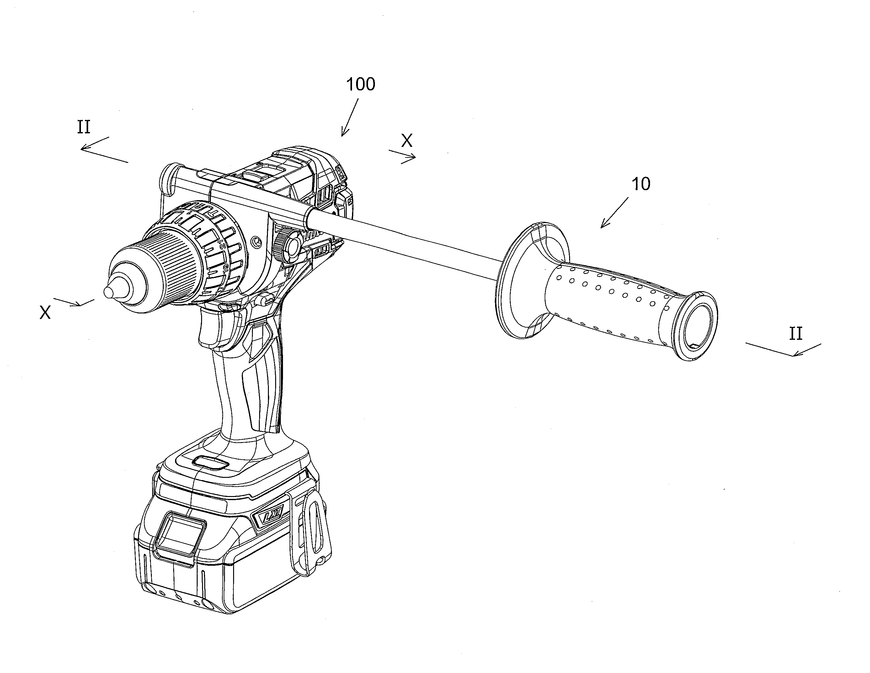
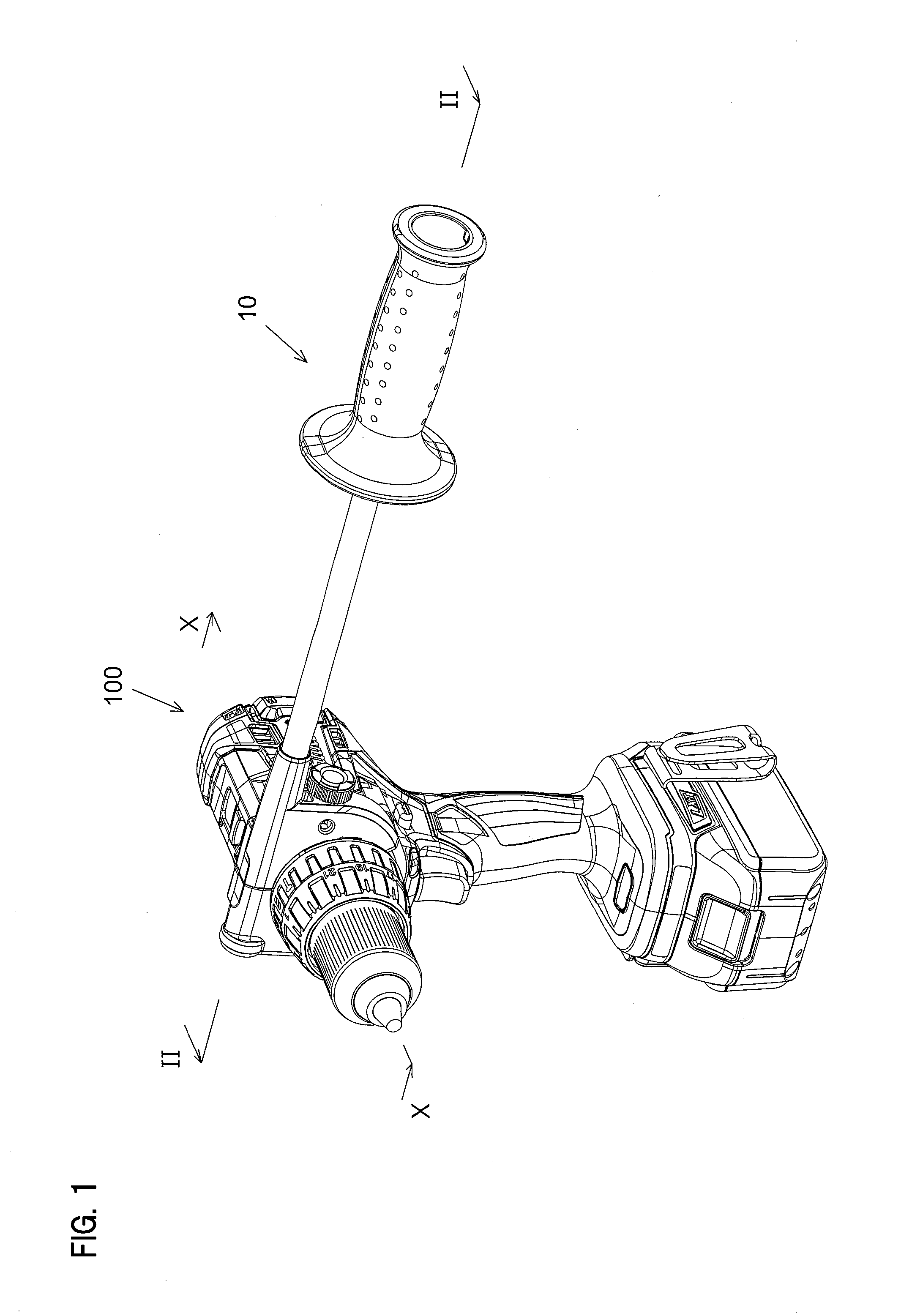
[0046]Each of the additional features and method steps disclosed above and below may be utilized separately or in conjunction with other features and method steps to provide and manufacture improved auxiliary handles and method for using such auxiliary handles and devices utilized therein. Representative examples of the invention, which examples utilized many of these additional features and method steps in conjunction, will now be described in detail with reference to the drawings. This detailed description is merely intended to teach a person skilled in the art further details for practicing preferred aspects of the present teachings and is not intended to limit the scope of the invention. Only the claims define the scope of the claimed invention. Therefore, combinations of features and steps disclosed within the following detailed description may not be necessary to practice the invention in the broadest sense, and are instead taught merely to particularly describe some represent...


PUM

PropertyMeasurementUnit
Angleaaaaaaaaaa
Timeaaaaaaaaaa
Diameteraaaaaaaaaa

Abstract

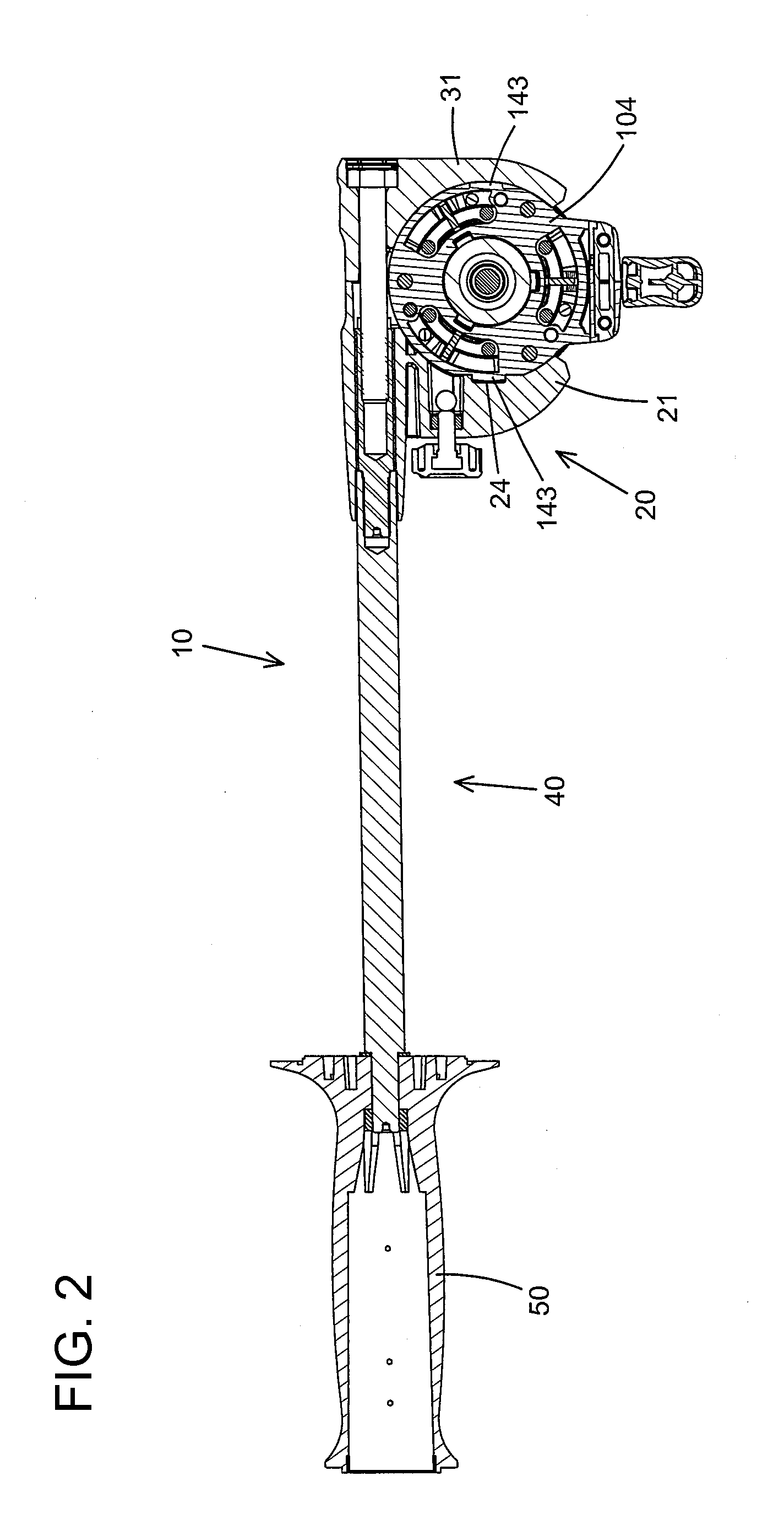
An auxiliary handle (10) comprises a first clamp member (21), a second clamp member (31), an operation rod (40) and a grip (50). By rotation of the operation rod (40), the first clamp member (21) is moved toward a distal end of the operation rod (40), and at the same time, the second clamp member (31) is moved toward a base end of the operation rod (40). Accordingly, the first clamp member (21) and the second clamp member (31) are moved to be close to each other. As a result, an auxiliary handle attachable part (140) of a screw driver (100) is clamped by the first clamp member (21) and the second clamp member (31), and thereby the auxiliary handle (10) is attached to the screw driver (100).

Description

CROSS REFERENCE TO RELATED APPLICATION[0001]The present application claims priority from Japanese Patent Applications No. 2013-268138 filed on Dec. 25, 2013, the entire contents of which are incorporated by reference herein.FIELD OF THE INVENTION[0002]The present invention relates to an auxiliary handle which is attached to a power tool and the power tool having the same.BACKGROUND OF THE INVENTION[0003]U.S. No. 2011 / 0120741 discloses an auxiliary handle which is attached to a power tool. The auxiliary handle comprises a first clamp member, a second clamp member, a rod and a grip. The auxiliary handle is attached to the power tool by clamping a gear housing of the power tool by the first and the second clamp members.SUMMARY OF THE INVENTION[0004]In the auxiliary handle described above, the first clamp member is fixed on a tip end of the rod. Accordingly, by moving the second clamp member toward the first clamp member fixed on the tip end of the rod, the gear housing of the power too...

Claims


Application Information

Patent Timeline
IPC IPC(8): B25F5/02B23B45/00
CPCB25F5/026B23B45/003B23B45/001B25F5/008B25F5/02
Inventor KAMIYA, TAKESHI
Owner MAKITA CORP
Learn More