Accessory mounting structure
- Summary
- Abstract
- Description
- Claims
- Application Information
AI Technical Summary
Benefits of technology
Problems solved by technology
Method used
Image
Examples
Embodiment Construction
[0029]An embodiment of the present invention will be described in detail with reference to the accompanying drawings.
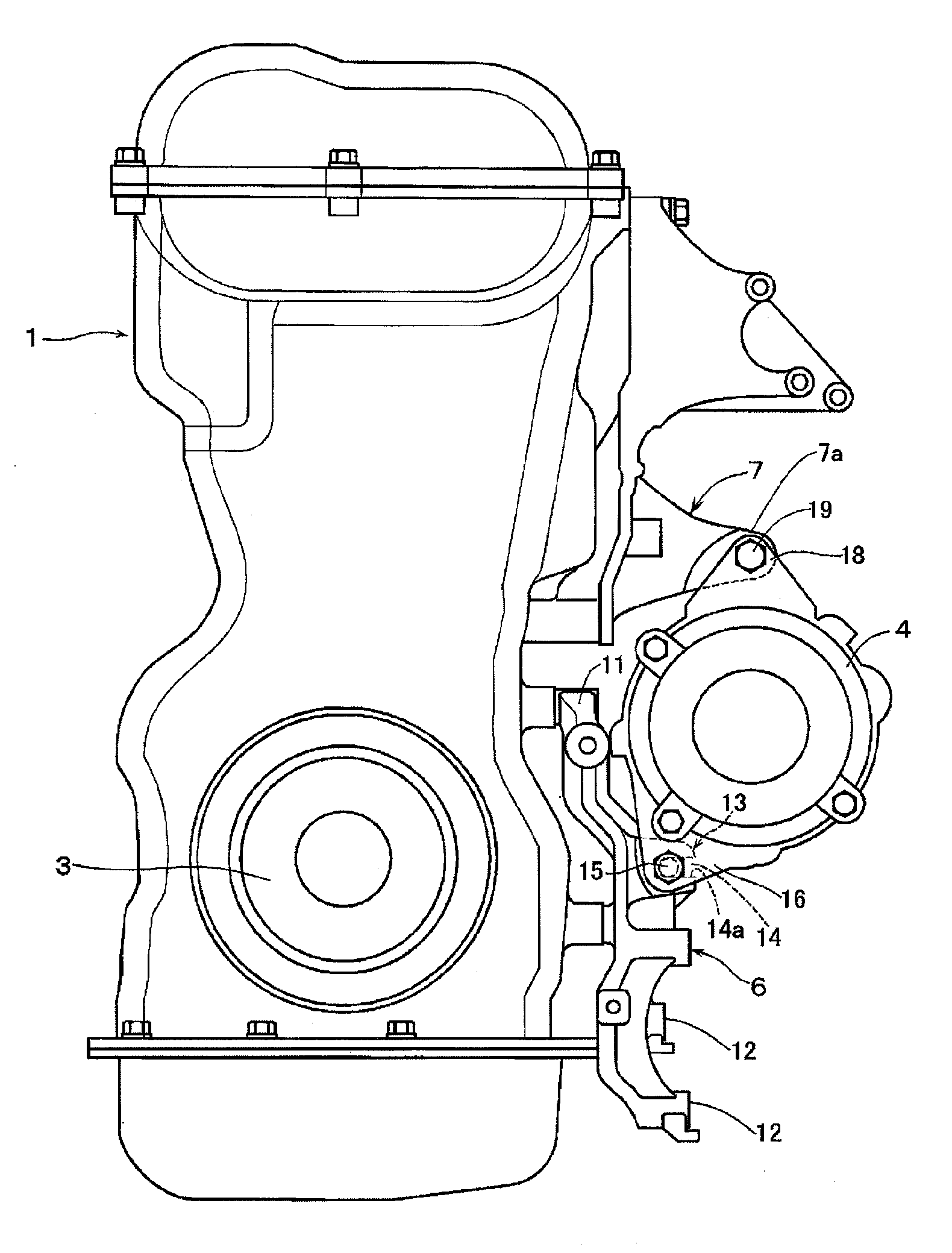
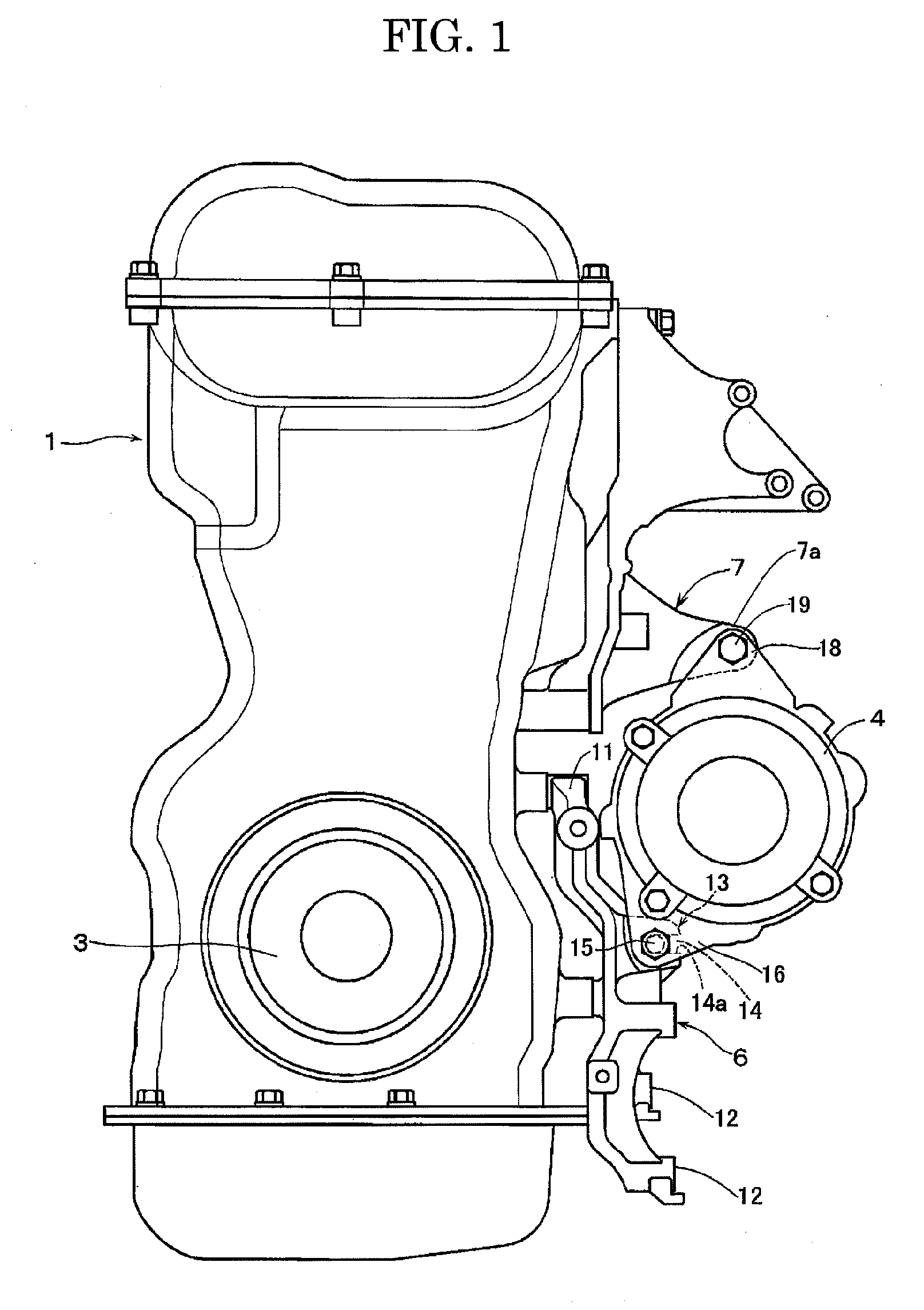
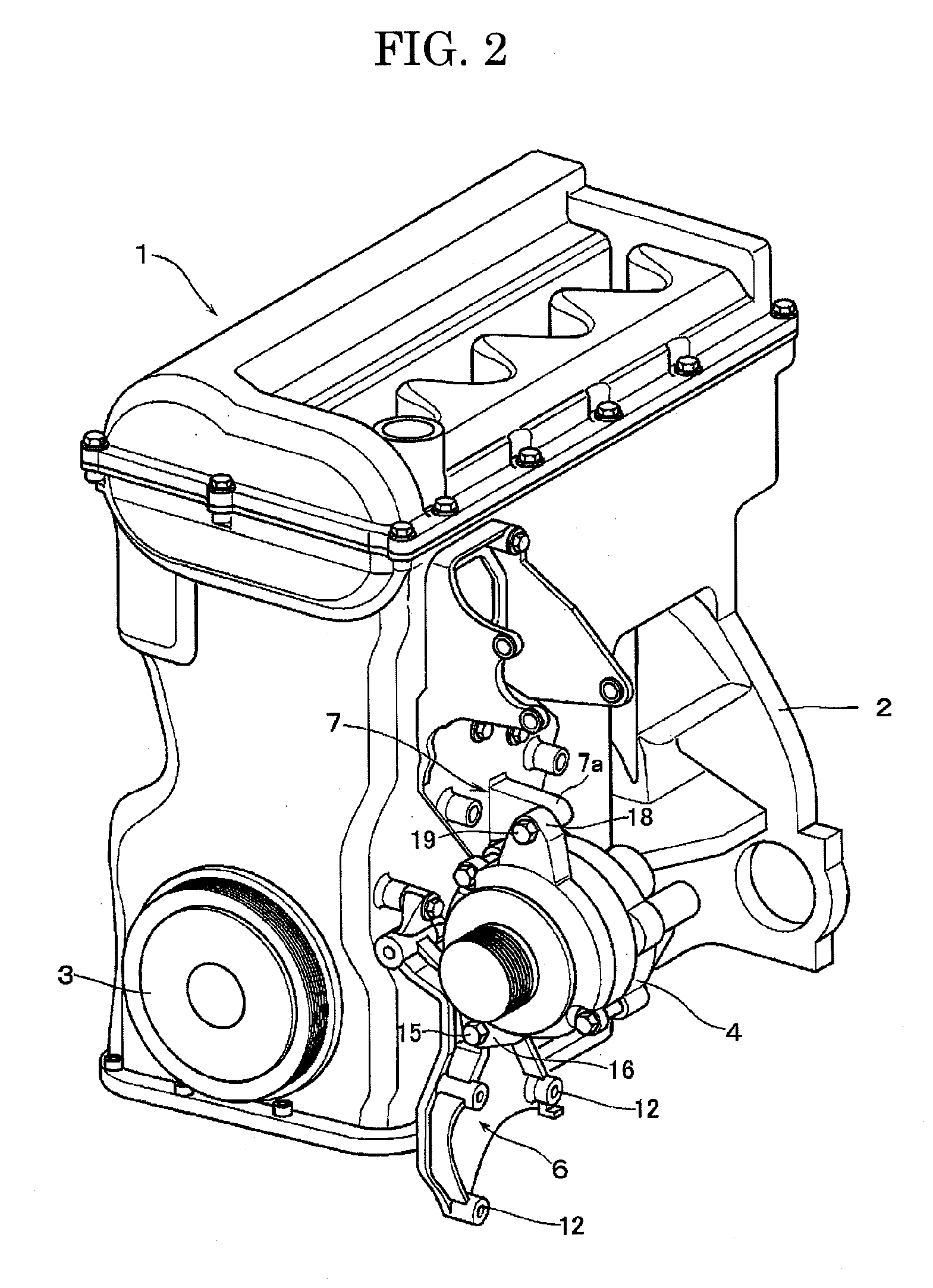
[0030]As shown in FIGS. 1 and 2, a vehicle engine (engine) 1 is an in-line multi-cylinder engine, and a crankshaft pulley 3 connected to a crankshaft is disposed at the front of a cylinder block 2 of the engine 1. On the other hand, an alternator 4 is held, as an accessory, beside the side surface of the cylinder block 2. Further, a power steering pump and an air compressor are held beside the side surface of the cylinder block 2.
[0031]A pulley of an accessory, such as the alternator 4, is disposed on the same plane as the crankshaft pulley 3, and a belt is looped over the crankshaft pulley 3 and the pulley of the accessory via an idler pulley and a tension pulley. By so doing, the drive force of the crankshaft of the engine 1 is transmitted to the accessory such as the alternator 4.
[0032]As shown in FIGS. 1 to 5, an alternator bracket 6 as an accessory mounting brack...
PUM
 Abstract
Description
Claims
Application Information
 - R&D
- Intellectual Property
- Life Sciences
- Materials
- Tech Scout
- Unparalleled Data Quality
- Higher Quality Content
- 60% Fewer Hallucinations
Browse by: Latest US Patents, China's latest patents, Technical Efficacy Thesaurus, Application Domain, Technology Topic, Popular Technical Reports.
© 2025 PatSnap. All rights reserved.Legal|Privacy policy|Modern Slavery Act Transparency Statement|Sitemap|About US| Contact US: help@patsnap.com


