Master cylinder hydraulic fluid flow control valve, master cylinder provided with the master cylinder hydraulic fluid flow control valve, and brake device provided with master cylinder

a technology of hydraulic fluid flow control and master cylinder, which is applied in the direction of rotary clutches, hydraulic couplings, brake devices, etc., can solve the problems of impaired hydraulic fluid flow control function of the master cylinder hydraulic fluid flow control valve a, suppress deformation of the sealing member or damage to the sealing member, and improve the sealing property of the sealing member , the effect of reducing the pushing for

Inactive Publication Date: 2012-08-16
BOSCH CORP
View PDF3 Cites 2 Cited by
  • Summary
  • Abstract
  • Description
  • Claims
  • Application Information

AI Technical Summary

Benefits of technology

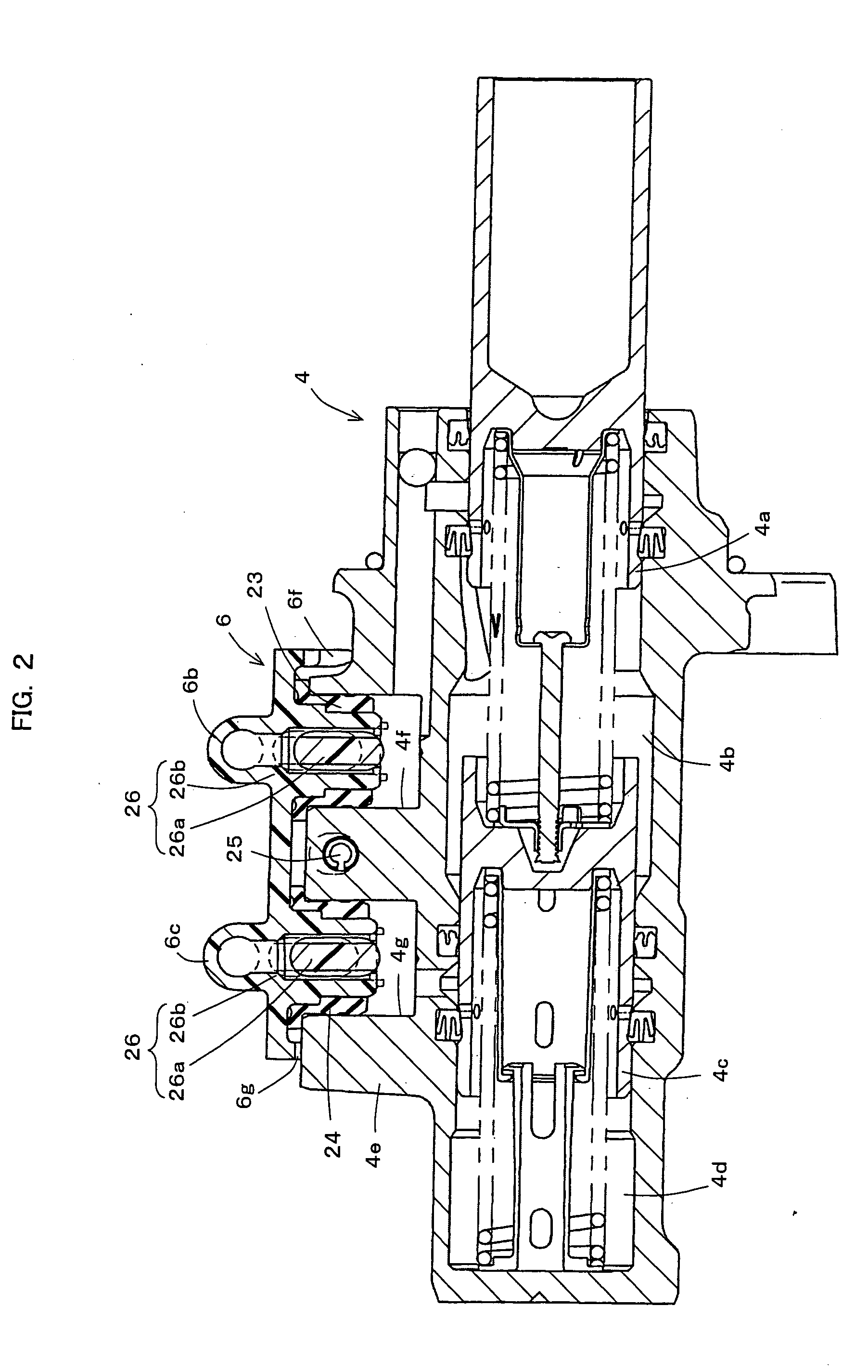
[0019]According to the master cylinder hydraulic fluid flow control valve of the present invention having such a constitution, the floating valve element is vertically movably accommodated in the cylindrical member which is hermetically mounted on the master cylinder by the sealing member and forms the fluid passage therein, and the valve seat is arranged in the cylindrical member. Due to such a constitution, the floating valve element is not brought into contact with the sealing member. Accordingly, when the floating valve element is seated on the valve seat at the time of releasing the operation of the automatic brake, it is possible to prevent a force applied to the floating valve element by a fluid pressure from a hydraulic chamber side of the master cylinder from acting on the sealing member. Further, a pressure receiving area of the sealing member is small and hence, it is possible to decrease a pushing force applied to the sealing member due to a fluid pressure from the hydraulic chamber side of the master cylinder. As a result, the deformation of the sealing member or the damage on the sealing member can be suppressed and hence, the sealing property of the sealing member can be favorably maintained.
[0020]Further, the floating valve element and the valve seat are arranged in the inside of the cylindrical member and hence, a pressure receiving area of the floating valve element when the floating valve element is seated on the valve seat can be decreased. Accordingly, a force which pushes up the valve seat and is generated by a force applied to the floating valve element by a fluid pressure from the hydraulic chamber side when an operation of the automatic brake is released can be decreased. Accordingly, the seating posture of the floating valve element on the valve seat can be stably held. As a result, a hydraulic fluid flow control function of the master cylinder hydraulic fluid flow control valve can be favorably maintained. Particularly, the floating valve element can be formed into an axially elongated circular columnar shape. Accordingly, the inclining of the floating valve element can be suppressed and hence, the seating posture of the floating valve element on the valve seat can be brought into a more stable state. Further, the upper end surface of the floating valve element which constitutes a seating surface of the floating valve element on the valve seat is formed into a spherical shape and hence, even if the floating valve element is slightly inclined, it is possible to bring the seating posture of the floating valve element on the valve seat into a stable state more effectively.
[0021]Further, the throttle passage which penetrates the floating valve element in the axial direction of the floating valve element and throttles the flow of the hydraulic fluid is arranged in the floating valve element, and in a state where the floating valve element is seated on the valve seat, the reservoir tank side with respect to the valve seat and the master cylinder side with respect to the valve seat are communicated with each other only through the throttle passage. Accordingly, even when a state where the floating valve element is seated on the valve seat is held, it is possible to prevent a pressure from remaining in the hydraulic chamber of the master cylinder eventually. By properly setting a flow passage area of the throttle passage, a throttle quantity of the flow of a hydraulic fluid can be set to various values. Particularly, by forming the throttle passage by the groove formed on the outer peripheral surface of the floating valve element, the throttle passage can be easily formed.
[0022]Further, the stopper for preventing the removal of the floating valve element is formed on an inner side of the lower end of the cylindrical member in a projecting manner. Due to such a constitution, the removal of the floating valve element accommodated in the cylindrical member from the cylindrical member can be prevented. Accordingly, it is possible to prevent the removal of the floating valve element which is assembled to the cylindrical member in advance and hence, the falling of the floating valve element or the removal of the floating valve element at the time of mounting the cylindrical member on the master cylinder can be prevented. Accordingly, it is unnecessary to inspect the floating valve element one by one at the time of mounting the cylindrical member on the master cylinder and hence, the number of operation man-hours can be decreased accordingly.
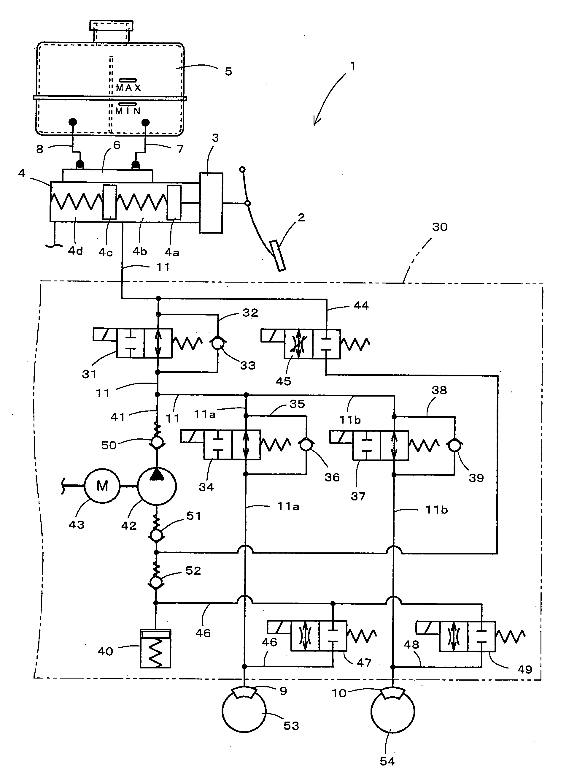
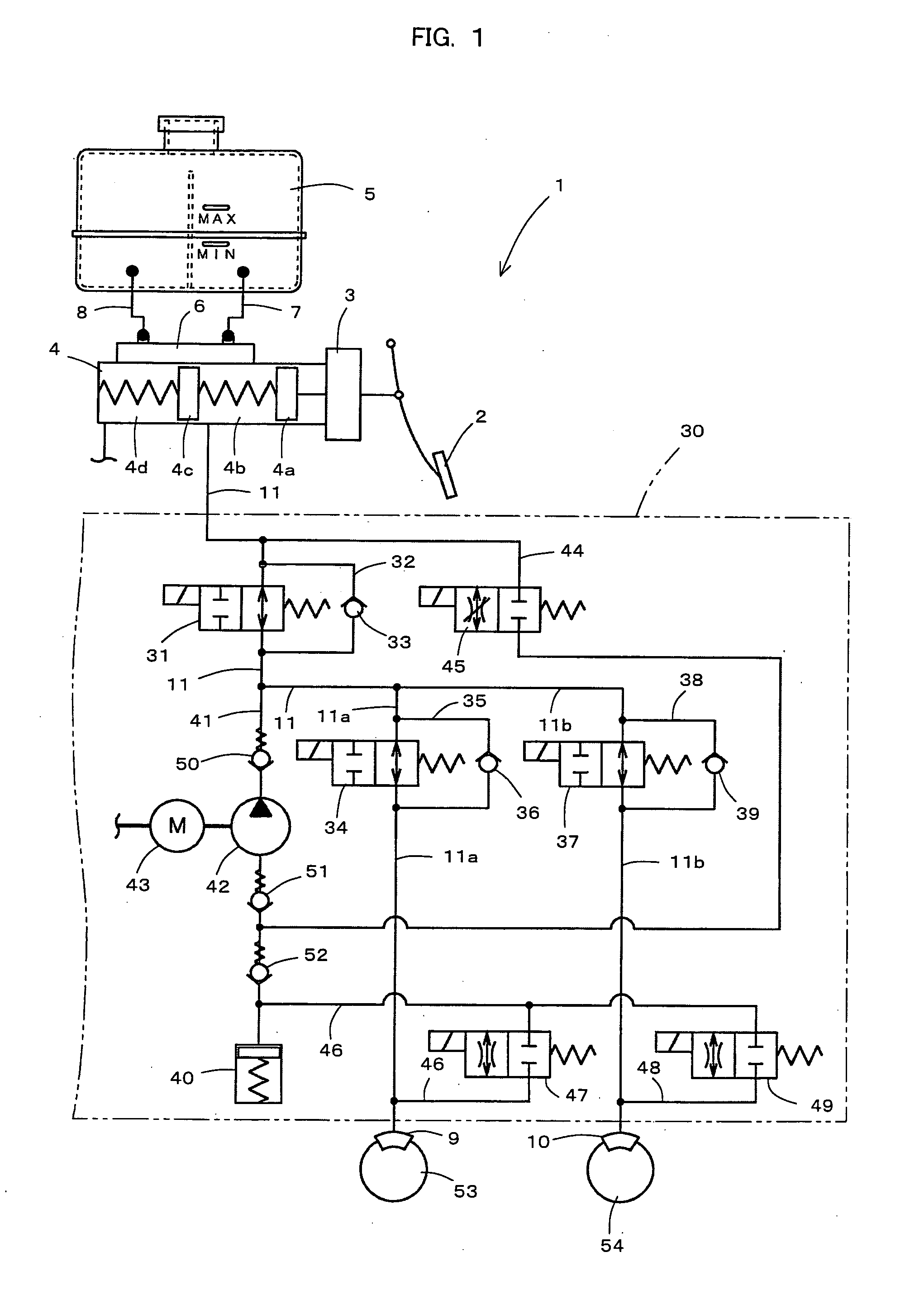
[0023]Further, the master cylinder of the present invention includes the master cylinder hydraulic fluid flow control valve according to the present invention. Accordingly, a hydraulic fluid flow control function of the master cylinder hydraulic fluid flow control valve can be favorably maintained and hence, the property of discharging and supplying a hydraulic fluid can be surely ensured at the time of performing usual braking by operating the master cylinder and at the time of performing automatic braking by not operating the master cylinder. Accordingly, the respective operational reliabilities of the normal brake and the automatic brake can be enhanced.
[0024]Further, the brake device of the present invention includes the master cylinder according to the present invention. Accordingly, as described previously, the master cylinder can enhance the respective operational reliabilities of the normal brake and the automatic brake and hence, both the normal brake and the automatic brake can be surely operated.

Problems solved by technology

Further, due to the deformation of the valve seat member h or the damage on the valve seat member h, the seating posture of the floating valve element e becomes unstable thus giving rise to a possibility that an hydraulic fluid flow control function of the master cylinder hydraulic fluid flow control valve a is impaired.

Method used


Image

  • Master cylinder hydraulic fluid flow control valve, master cylinder provided with the master cylinder hydraulic fluid flow control valve, and brake device provided with master cylinder
  • Master cylinder hydraulic fluid flow control valve, master cylinder provided with the master cylinder hydraulic fluid flow control valve, and brake device provided with master cylinder
  • Master cylinder hydraulic fluid flow control valve, master cylinder provided with the master cylinder hydraulic fluid flow control valve, and brake device provided with master cylinder

Examples


Embodiment Construction

[0031]Hereinafter, a mode for carrying out the present invention is explained in conjunction with drawings.

[0032]FIG. 1 is a view schematically showing a brake device which is provided with one example of an embodiment of a reservoir tank connecting connector according to the present invention.

[0033]As shown in FIG. 1, a hydraulic brake device 1 of this embodiment is basically equal to a conventionally known general hydraulic brake device of two systems. That is, the hydraulic brake device 1 includes: a brake pedal 2; a booster 3, a tandem master cylinder 4; a reservoir tank 5; a reservoir tank connecting connector 6; hoses 7, 8 which constitute hydraulic fluid supply pipes of two systems; brake cylinders of two systems; and hydraulic fluid pressure passages of two systems. Here, brake hydraulic systems of two systems on a brake cylinder side with respect to the tandem master cylinder 4 have the same constitution. Accordingly, FIG. 1 shows one brake hydraulic system and the explanat...


PUM


Abstract

Provided is a master cylinder hydraulic fluid flow control valve which can effectively decrease a pressure receiving area of a floating valve element when the floating valve element is seated on a valve seat, can favorably maintain a sealing function of a sealing member, and can suppress the increase of the number of assembling operation man-hours.
A floating valve element 26a is vertically movably accommodated in a master cylinder connecting nipple portion 6b2, 6c2 which is hermetically mounted on a tandem master cylinder 4 by sealing members 23, 24 and forms a fluid passage between a reservoir tank and a tandem master cylinder 4 therein, and a valve seat 26b on which the floating valve element 26a is seatable is arranged in the master cylinder connecting nipple portion 6b2, 6c2.

Description

TECHNICAL FIELD[0001]The present invention relates to a technical field of a master cylinder hydraulic fluid flow control valve which is used in a hydraulic pressure-actuated device such as a hydraulic brake device which makes use of a fluid pressure such as an oil pressure and controls the flow of a hydraulic fluid between a master cylinder which generates a fluid pressure and a reservoir tank, a technical field of a master cylinder which includes the master cylinder hydraulic fluid flow control valve, and a technical field of a brake device which includes the master cylinder.BACKGROUND ART[0002]Conventionally, with respect to vehicles such as automobiles, there has been known a vehicle which adopts a hydraulic brake device as a hydraulic pressure-actuated device which makes use of a fluid pressure. As such a hydraulic brake device, there has been known a hydraulic brake device where an automatic brake device which performs a traction control or the like based on a brake operation ...

Claims


Application Information

Patent Timeline
Patent Type & Authority Applications(United States)
IPC IPC(8): B60T11/28B60T11/26F16K31/18
CPCB60T11/232Y10T137/7426
Inventor TAKAHASHI, TOSHIYUKI
Owner BOSCH CORP
Why Eureka
Try Eureka