Swirling vane wheel accumulating apparatus

Active Publication Date: 2012-12-13
FUJITSU FRONTECH LTD
View PDF18 Cites 1 Cited by
  • Summary
  • Abstract
  • Description
  • Claims
  • Application Information

AI Technical Summary

Benefits of technology

[0027]With the swirling vane wheel accumulating apparatus according to the present invention, paper sheets are entered in the accumulation part by causing the paper sheets to curve in the shape of large U. Therefore, even damaged banknotes or forms with low stiffness are held by the vane wheel without hanging down despite being beaten by the vanes, and are disengaged from the vane wheel, whereby the banknotes or the forms can be stably accumulated in the accumulation part without causing jamming.
[0028]Additionally, with the swirling vane wheel accumulating apparatus according to the present invention, paper sheets are continuously curved in the sha

Problems solved by technology

Incidentally, banknotes that customers deposits into an ATM or the like are not always neat in shape.
For example, the reject storing unit is a storing unit for storing a banknote that is badly damaged by being folded, wrinkled, torn or the like and has a problem in future use, and an old banknote that is currently discontinued.
Therefore, the banknote is disengaged from the vane wheels before reaching the stoppers, leading to an unstable state or jamming caused by the still engaged rear end of the banknote in many cases.
If the front end of the banknote hangs down, the banknote cannot go into the gap between the vanes of the vane wheel, and gets stuck immediately below the entrance slot of the storing unit with the rear end folded subsequently to the portion that hangs down and is not held by the vane wheel, so t

Method used


Image

  • Swirling vane wheel accumulating apparatus
  • Swirling vane wheel accumulating apparatus
  • Swirling vane wheel accumulating apparatus

Examples


first embodiment

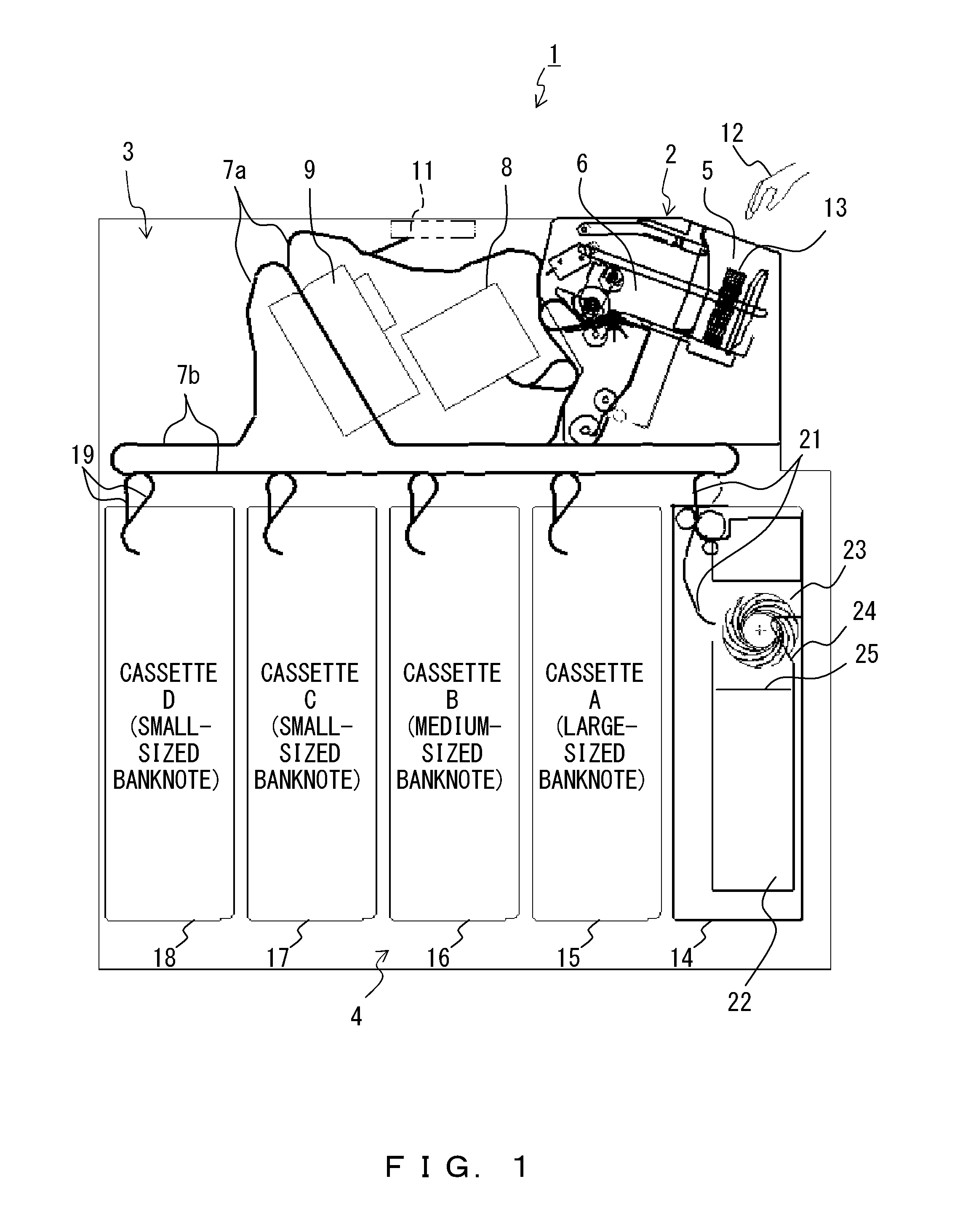
[0039]FIG. 1 is a cross-sectional view schematically illustrating a configuration of an ATM (Automated Teller Machine) (hereinafter referred to also as a main body apparatus) including a swirling vane wheel accumulating apparatus according to the first embodiment. The ATM 1 illustrated in this figure includes a banknote deposit / withdrawal device 2, a conveying unit 3 and a storing unit 4.

[0040]The banknote deposit / withdrawal device 2 has, on an upper surface formed to slightly tilt in a front (right) portion of the device, an input operation panel unit, not illustrated because of being cross-sectioned, a deposit / withdrawal unit 5 having a shutter in an upper opening, and a temporarily accumulating unit 6 for temporarily storing accumulated banknotes.

[0041]In the conveying unit 3, conveyance paths 7 (7a, 7b) are arranged by being crisscrossed. Each of the conveyance paths 7 is actually composed of many rollers, many belts bridged over the rollers, switching gates respectively arrange...


PUM


Abstract

Large-diameter entry rollers, and small-diameter entry rollers pressing against the large-diameter entry rollers via a conveyance belt enter a paper sheet in an accumulation part via an entrance slot. A central upper guide member makes contact with an upper surface of a central portion of the banknote. Both sides lower guide members guide the banknote while causing the banknote to curve in the shape of large U in a direction orthogonal to a conveyance direction of the banknote by lifting up both ends of the banknote entered in the accumulation part with the use of an upwardly curved tip. The front end of the banknote does not hang down despite being beaten by vanes, and the banknote goes between the vanes. The banknote is rotationally conveyed, hits the stoppers to stop, is disengaged from a swirling vane wheel, and is accumulated.

Description

CROSS REFERENCE TO RELATED APPLICATION[0001]This application is based upon and claims the benefit of priority from prior Japanese Application No. 2011-131311, filed Jun. 13, 2011, the entire contents of which are incorporated herein by reference.BACKGROUND OF THE INVENTION[0002]1. Field of the Invention[0003]The present invention relates to a swirling vane wheel accumulating apparatus, and more particularly, to a swirling vane wheel accumulating apparatus in a paper sheet accumulating apparatus, available also alone as a reject storing unit for storing a banknote identified as being defective or deformed in an ATM (Automated Teller machine) or the like, or as an organizing machine of forms or a counter of valuable instruments.[0004]2. Description of the Related Art[0005]Conventionally, swirling vane wheel accumulating apparatuses for storing banknotes in a banknote storing unit by using a vane wheel provided with swirling vanes as a banknote storing mechanism of an ATM or the like a...

Claims


Application Information

Patent Timeline
IPC IPC(8): B65G29/00
CPCB65H29/40B65H29/62B65H29/70B65H31/10G07D11/0081B65H2701/1912B65H2301/4474B65H2220/01B65H2220/02G07D11/40G07D2211/00G07F19/201G07D11/16
Inventor KATO, HARUYASUNISHIDA, MITSUTAKAMINAMISHIN, HAYATO
Owner FUJITSU FRONTECH LTD
Why Eureka
Try Eureka