Bird strike prevention device for jet engine, and airplane incorporating the same

a technology of preventing device and jet engine, which is applied in the direction of separation process, auxillary pretreatment, filtration separation, etc., can solve the problems of large volume of airflow, large financial loss, and ineffective screening of the front of the jet engin

Inactive Publication Date: 2015-06-25
ALNAFISAH KHALID HAMAD MUTLEB
View PDF19 Cites 15 Cited by
  • Summary
  • Abstract
  • Description
  • Claims
  • Application Information

AI Technical Summary

Benefits of technology

[0010]In one embodiment, a bird strike prevention device for covering an air intake of a jet engine of an airplane includes: a plurality of stays arranged to form substantially a conical shape as a whole, and a joining portion configured to connect the plurality of stays to each other on an apex side of substantially the conical shape. The plurality of stays is mounted on the...

Problems solved by technology

Thus, a large volume of airflow is required to operate the jet engine, and sometime a bird may be ingested with the airflow.
However, even with such a prevention measure against the bird strike, airplanes may still suffer damage and be forced to return to airports, resulting great financial losses.
According t...

Method used


Image

  • Bird strike prevention device for jet engine, and airplane incorporating the same
  • Bird strike prevention device for jet engine, and airplane incorporating the same
  • Bird strike prevention device for jet engine, and airplane incorporating the same

Examples


first embodiment

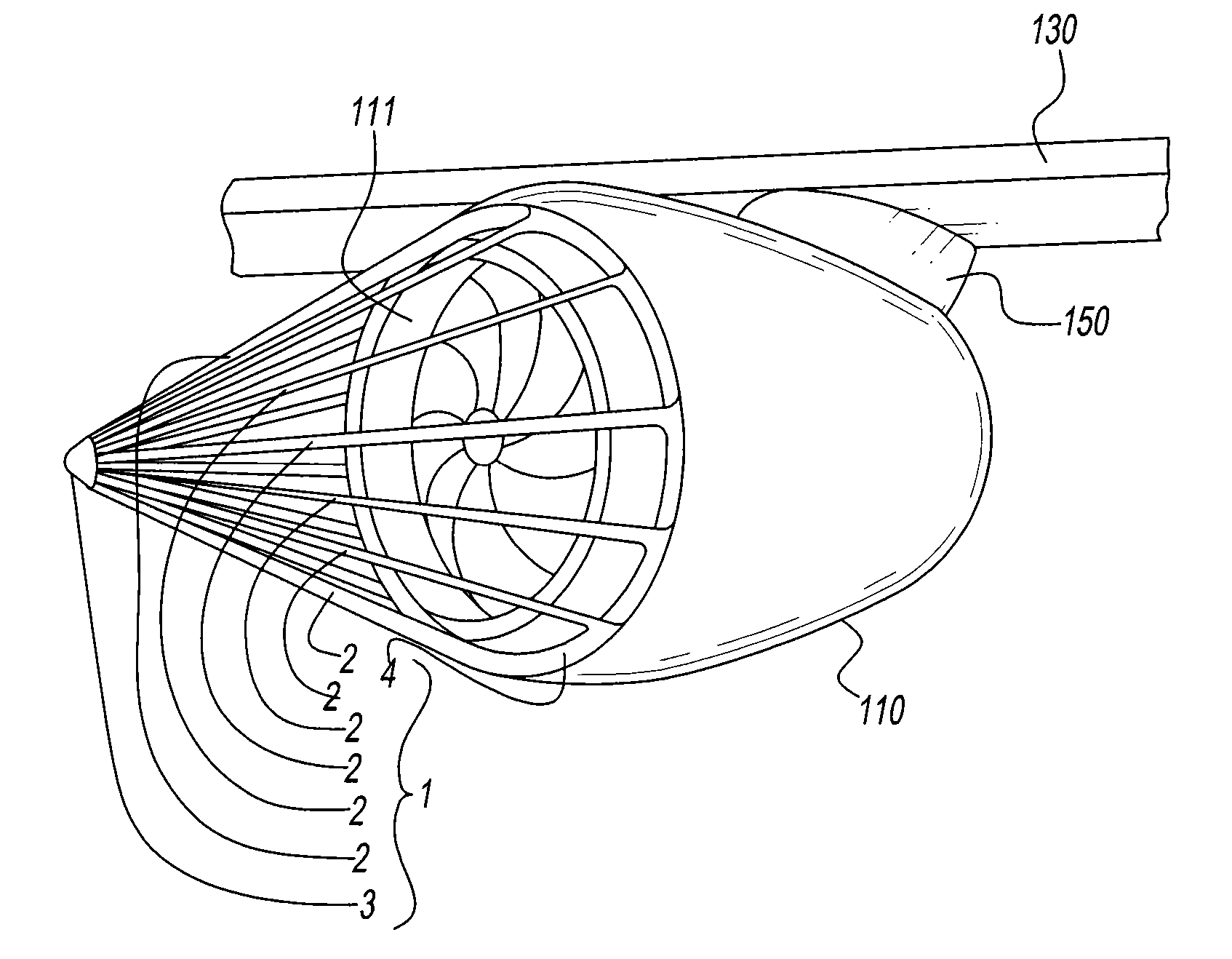
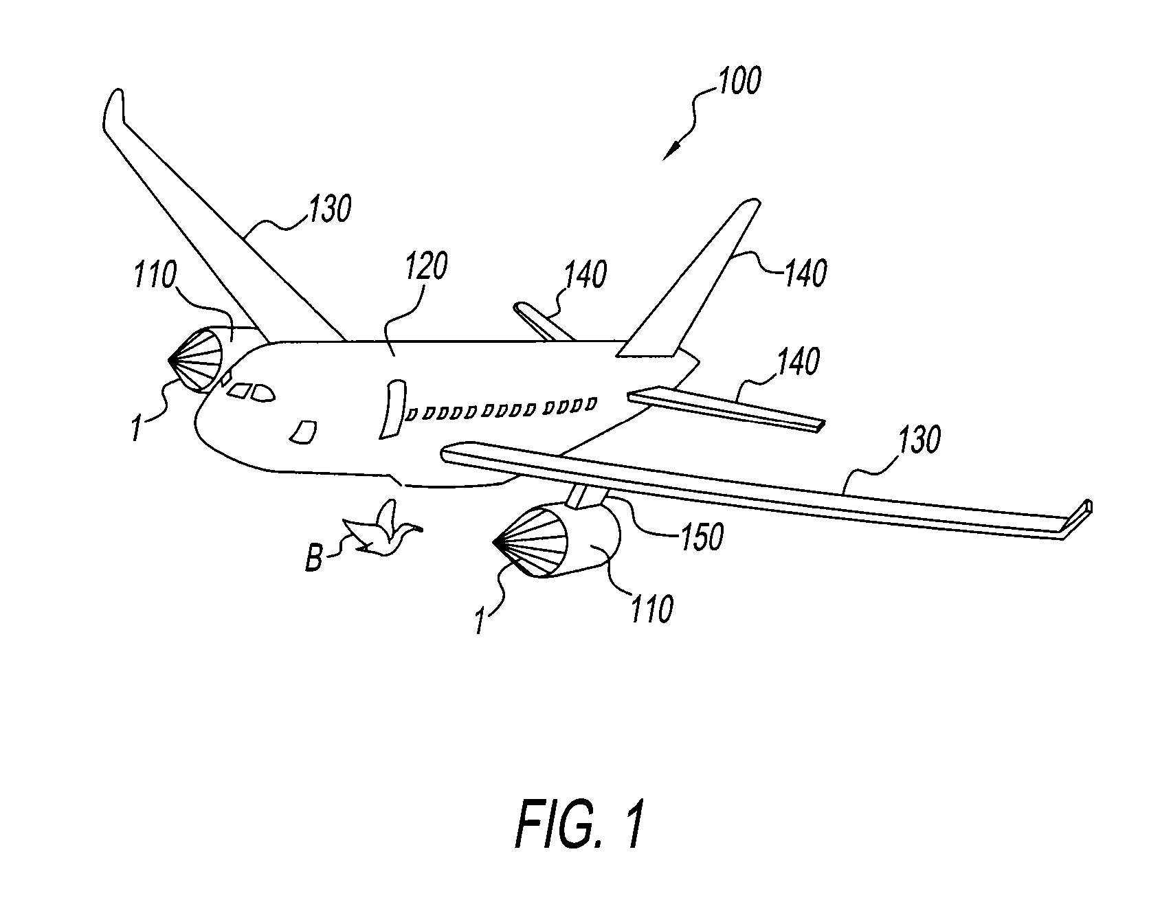
[0026]The first embodiment is now described with reference to FIG. 1 to FIG. 4. As illustrated in FIG. 1, in the present embodiment, an airplane 100 including bird strike prevention devices 1 is a passenger airplane and has two jet engines 110. FIG. 1 illustrates an exemplary situation where the airplane 100 is flying close to a bird B.

[0027]In the following description, a direction toward the nose of the airplane 100 will be referred to as a front direction, and a direction opposite to the front direction is referred to as a rear direction. Further, an up-down direction and a right-left direction are defined relative to a traveling direction of the airplane 100 or a viewing direction of a pilot operating the airplane 100.

[0028]Referring to FIG. 1, the airplane 100 includes jet engines 110, a fuselage 120, wings 130, and tails 140. The jet engines 110 are fixed under the right and left wings 130 with pylons 150. The bird strike prevention device 1 is mounted in the front of each jet...

second embodiment

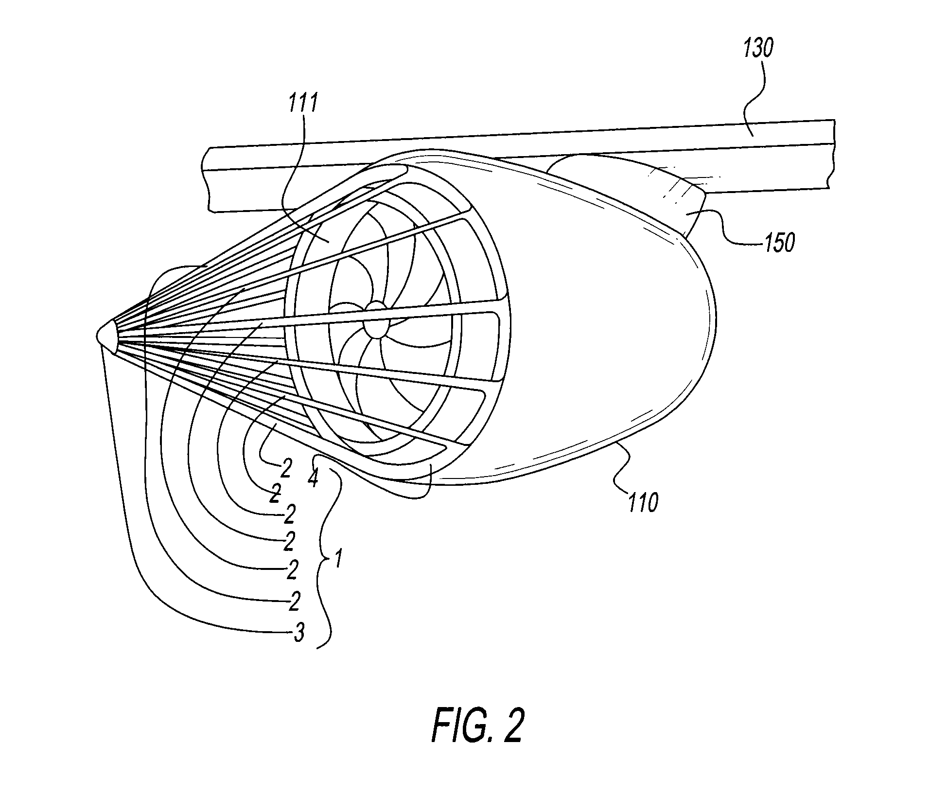
[0051]Next, the second embodiment is described with reference to FIG. 5A / B to FIG. 9. As is the case with the first embodiment, the second embodiment is directed to the bird strike prevention device 1 mounted over the air intake 111 of the jet engine 110 of the airplane 100 as illustrated in FIG. 1.

[0052]Referring to FIG. 5B, the bird strike prevention device 1 of the present embodiment has substantially a conical shape as a whole and covers the air intake 111 in such a way that the axis of the bird strike prevention device 1 substantially coincides with that of the jet engine 110, as in the case with the first embodiment.

[0053]However, in the present embodiment, the stays 2 are configured such that each stay 2 can be retracted and stowed under a skin cover (exterior surface) 112 of the jet engine 110 through openings 113 formed on the skin cover 112 as illustrated in FIG. 5A. In other words, the stays 2 are configured to have two operation modes, a mode in which the air intake 111 ...


PUM

PropertyMeasurementUnit
Lengthaaaaaaaaaa
Lengthaaaaaaaaaa
Angleaaaaaaaaaa

Abstract

A bird strike prevention device for covering an air intake of a jet engine of an airplane includes a plurality of stays arranged to form a conical shape as a whole; and a joining portion configured to connect the plurality of stays to each other on an apex side of the conical shape. The plurality of stays is mounted on the jet engine near an outer edge of the air intake at a base of the conical shape. An axis of the conical shape coincides with a rotation axis of the jet engine. The number of the stays included in the plurality of stays is determined based on a minimum size of target birds to be prevented from striking the jet engine.

Description

GRANT OF NON-EXCLUSIVE RIGHT[0001]This application was prepared with financial support from the Saudia Arabian Cultural Mission, and in consideration therefore the present inventor(s) has granted The Kingdom of Saudi Arabia a non-exclusive right to practice the present invention.BACKGROUND[0002]1. Field of the Disclosure[0003]This disclosure relates generally to bird strike prevention devices, and jet engines and airplanes including bird strike prevention devices. More specifically, this disclosure relates to bird strike prevention devices to be mounted near air intakes of airplane jet engines to protect the jet engines against bird strikes, and jet engines and airplanes including such bird strike prevention devices.[0004]2. Description of the Related Art[0005]Airplanes, especially passenger airplanes, use jet engines to generate thrust for flights. The jet engine takes air in through an air intake to generates the thrust by chemical reaction between oxygen contained in the air and ...

Claims


Application Information

Patent Timeline
IPC IPC(8): F02C7/055
CPCF02C7/055B64D33/02B01D46/0005B01D46/10B01D45/08F02C7/04Y02T50/60
Inventor ALNAFISAH, KHALID HAMAD MUTLEB
Owner ALNAFISAH KHALID HAMAD MUTLEB
Why Eureka
Try Eureka