Lens holder

a technology for lenses and holder plates, applied in the field of lenses holder plates, can solve the problem of not being able to remove the fixing part without showing, and achieve the effect of reducing the radius of curvature of the fixing arc, and saving time and capacity

Active Publication Date: 2015-06-25
AXIS
View PDF0 Cites 1 Cited by
  • Summary
  • Abstract
  • Description
  • Claims
  • Application Information

AI Technical Summary

Benefits of technology

[0006]This is advantageous in that the method for attaching is self-centering in a radial direction. Furthermore, when attaching the lens and compressing the compressible retainer, there is substantially no transfer in an axial direction. Additionally, the method is advantageous in that it is durable compared to, e.g., gluing. The method is also time and capacity efficient compared to, e.g., gluing and screwing. Furthermore, the force applied on the lens is more uniform compared to other types of attachments.
[0007]The method may further comprise the fixing part having a pressing part, the pressing part being at its ends connected to the fixing arc, and the step of reducing further comprising: pressing the pressing part thus reducing the radius of curvature of the fixing arc. An advantage with this is that it is simplifies the step of reducing the radius of curvature of the fixing arc. Another advantage is that it is not possible to remove the fixing part without it showing. If trying to remove the fixing part and then reattaching it, it will show on the fixing part. Thus, the method reduces the risk of tampering with the lens, lens holder, and, if the lens holder is attached to an image sensor, with the camera formed by these parts.
[0008]The method may further comprise the fixing part having a plurality of pressing parts, and the fixing arc having a plurality of arc portions, the pressing parts being at their ends connected to the arc portions, and the step of reducing further comprising: pressing the pressing parts thus reducing the radius of curvature of the fixing arc. This is advantageous in that the arc portions slide less against the compressible retainer during the reducing of the radius of curvature.
[0009]The step of pressing may further comprise: pressing by means of a predetermined force. This is advantageous in that the method may be automated. Another advantage is that a predetermined force will minimize the risk of damage while ensuring that the attachment is strong enough.

Problems solved by technology

Another advantage is that it is not possible to remove the fixing part without it showing.

Method used


Image

  • Lens holder
  • Lens holder
  • Lens holder

Examples


Embodiment Construction

[0036]The present invention will now be described more fully hereinafter with reference to the accompanying drawings, in which certain embodiments of the invention are shown. This invention may, however, be embodied in many different forms and should not be construed as limited to the embodiments set forth herein; rather, these embodiments are provided by way of example so that this disclosure will be thorough and complete, and will fully convey the scope of the invention to those skilled in the art. Like numbers refer to like elements throughout.

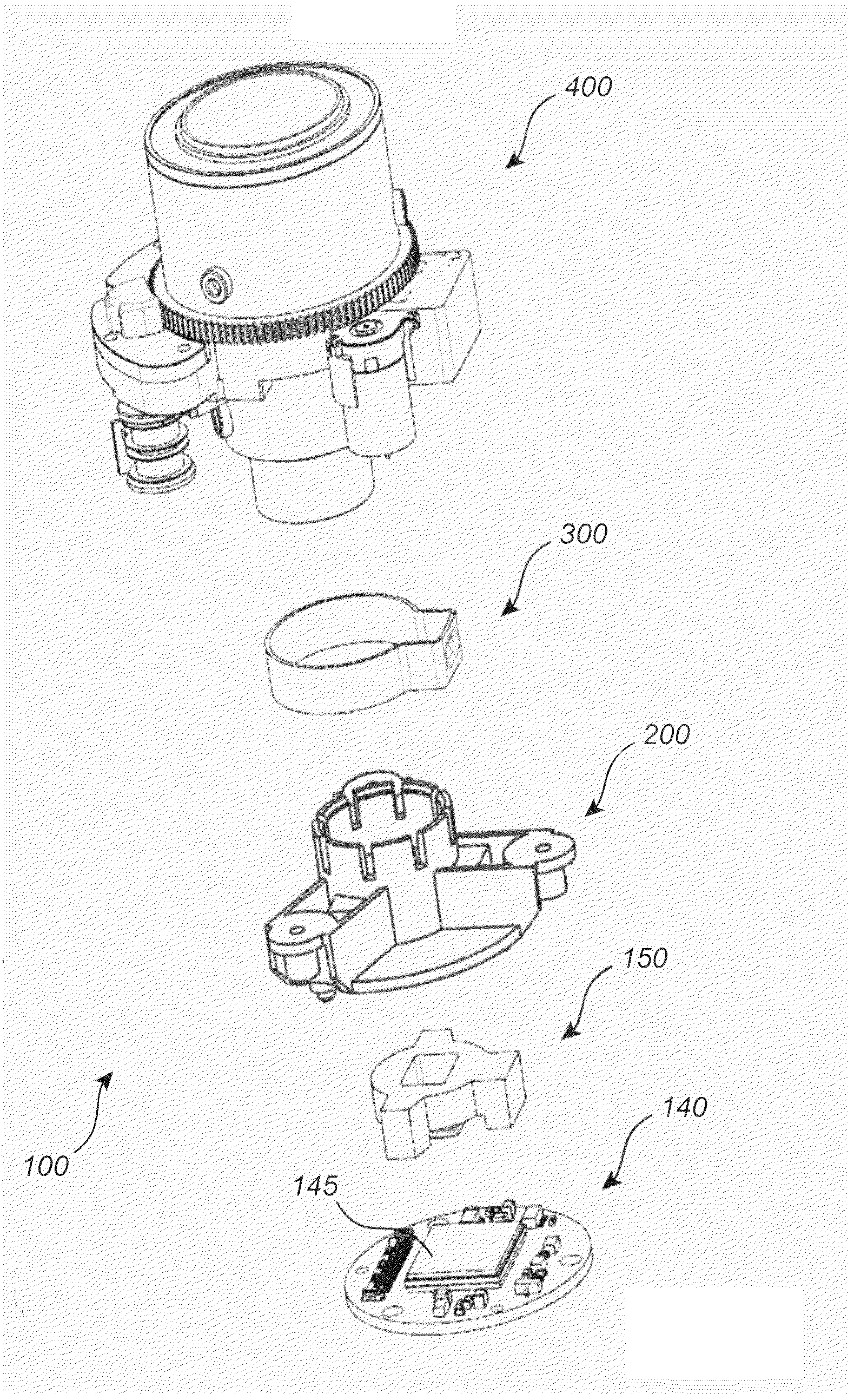
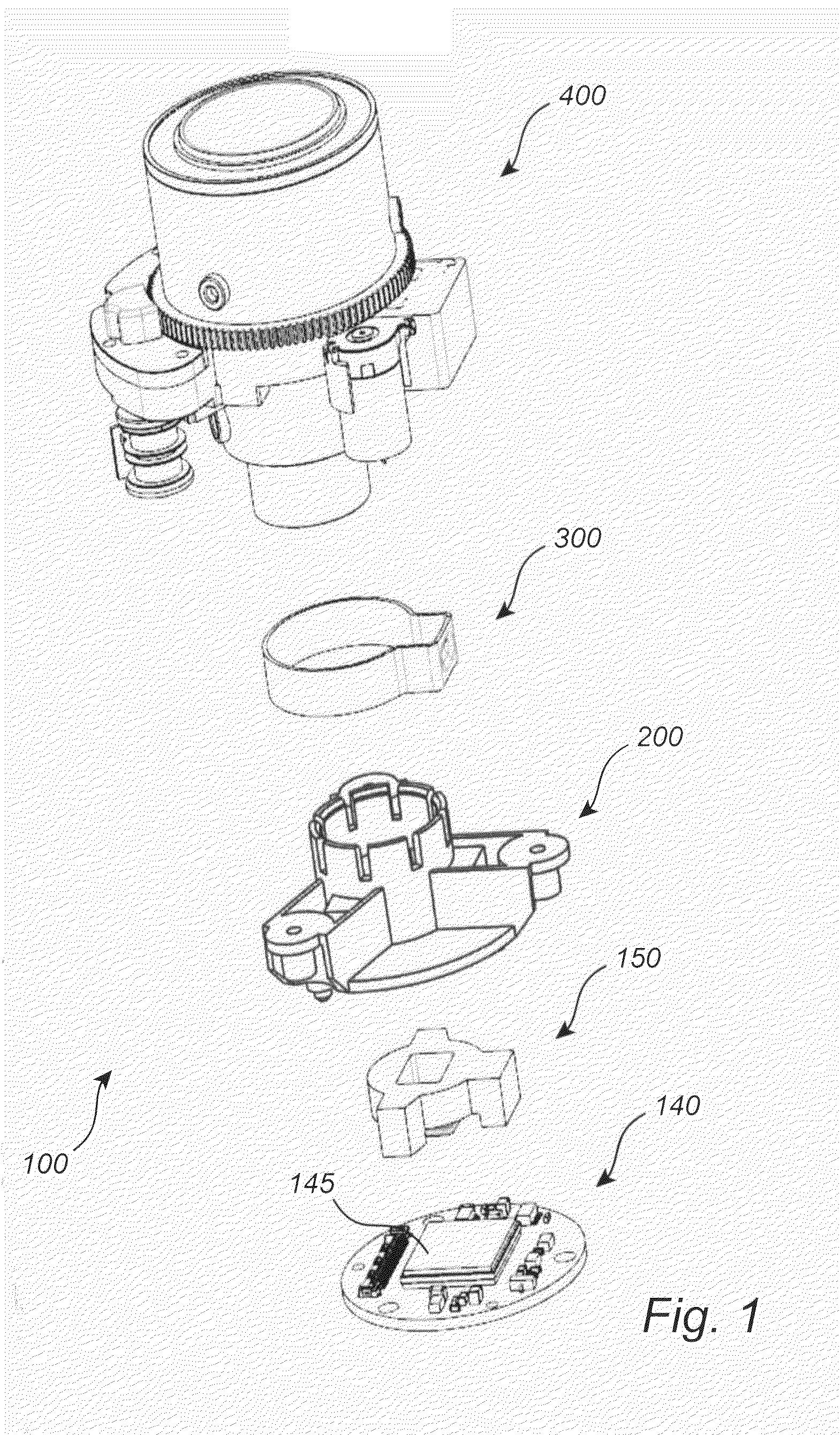
[0037]FIG. 1 is an exploded perspective view of an embodiment of the inventive arrangement for attaching a lens to a lens holder. The arrangement 100 comprises a lens holder 200 and a fixing part 300. In some embodiments the arrangement 100 also comprises a lens 400, and a PCB (printed circuit board) 140 having an image sensor 145. In a further embodiment the arrangement also comprises an insulating component 150. The insulating component 1...


PUM

PropertyMeasurementUnit
widthaaaaaaaaaa
radius of curvatureaaaaaaaaaa
distanceaaaaaaaaaa

Abstract

The present invention relates to a method, and an arrangement for attaching a lens to a lens holder. The method comprises: arranging a fixing arc of a fixing part around a compressible retainer of the lens holder, inserting an attachment portion of the lens into the compressible retainer, and reducing a radius of curvature of the fixing arc, such that the compressible retainer of the lens holder is compressed around the attachment portion, thereby attaching the lens to the lens holder.

Description

TECHNICAL FIELD[0001]The present invention relates to a method, and an arrangement for attaching a lens to a lens holder.BACKGROUND ART [0002]When attaching a lens to a network camera different solutions are used. The lens can, e.g., be glued to the camera. Gluing is however harmful to the environment and to the person involved in the gluing. Furthermore, gluing is complicated and involves several steps such as cleaning and curing. Additionally, glue can become dry and lose its gluing capacity.[0003]Another way to attach a lens to a network camera is by screwing a plurality of screws from the camera, radially, towards the lens. A disadvantage with this is that the lens can be mounted askew and that the mounting is time-consuming.SUMMARY OF THE INVENTION[0004]In view of the above, an objective of the invention is to solve or at least reduce one or several of the drawbacks discussed above. Generally, the above objective is achieved by the attached independent patent claims.[0005]Accor...

Claims


Application Information

Patent Timeline
Patent Type & Authority Applications(United States)
IPC IPC(8): G02B7/02G03B17/12
CPCG03B17/12G02B7/022G02B7/021G03B17/14G02B7/026Y10T29/49908
Inventor KULLGREN, FREDRIK
Owner AXIS
Why Eureka
Try Eureka