Floor Cleaning Apparatus and Touch-less Mopping System

a technology of floor cleaning and mopping system, which is applied in the field of mopping system, can solve the problems of overuse and/or acute muscular skeletal injuries, inability to reliably remove all dirt from the floor of the conventional mop and bucket system, and the type of injuries that have recently been the subject of research, so as to prevent the operator from being exposed, the effect of constant, rapid supply of re-cycled clean water

Inactive Publication Date: 2015-07-02
PURESSENCE VENTURES
View PDF1 Cites 11 Cited by
  • Summary
  • Abstract
  • Description
  • Claims
  • Application Information

AI Technical Summary

Benefits of technology

[0020]The touch-less mopping system provides a constant, rapid supply of re-cycled clean water by filtering and disinfecting waste water that is entered into a rinse tank after usage of a cleaning head in conjunction with the system. In preferred embodiments, the touch-less mopping system is configured to rinse and suction off contaminated water from the bottom portion of the cleaning head. This is all accomplished without the need for any operator effort or interaction.
[0021]The touch-less mopping system and its associated floor cleaning appara

Problems solved by technology

Conventional mop and bucket systems are not reliable in removing all dirt from a floor due to the tendency of the mop head, be it a sponge or fabric type, to permanently embed dirt and bacteria into the fibers of the mop head that are then re-deposited onto the floor.
Traditional mop systems also require repeated manual wringing and squeezing out of the mop head and lifting of the mop by the user, which is strenuous physical labor that may cause overuse and/or acute muscular skeletal injuries.
These types of injuries have recently been

Method used


Image

  • Floor Cleaning Apparatus and Touch-less Mopping System
  • Floor Cleaning Apparatus and Touch-less Mopping System
  • Floor Cleaning Apparatus and Touch-less Mopping System

Examples


Embodiment Construction

[0043]As disclosed herein, the term “Floor” refers to any hard surface upon which the mopping system may operate. For example, the disclosed mopping systems are designed to clean and disinfect floors comprising indoor and outdoor hard surfaces (as compared to carpeted and grassed) upon which a user can safely operate the mopping system 10. Floors may further comprise, for example, showers, and any surface made of one or more of the following materials: tile, marble, cement, concrete, glass, linoleum, etc.

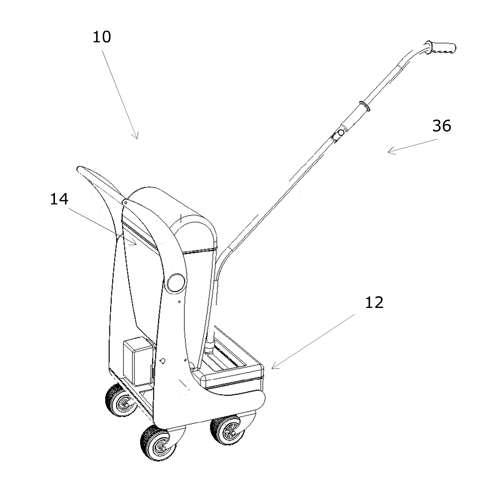
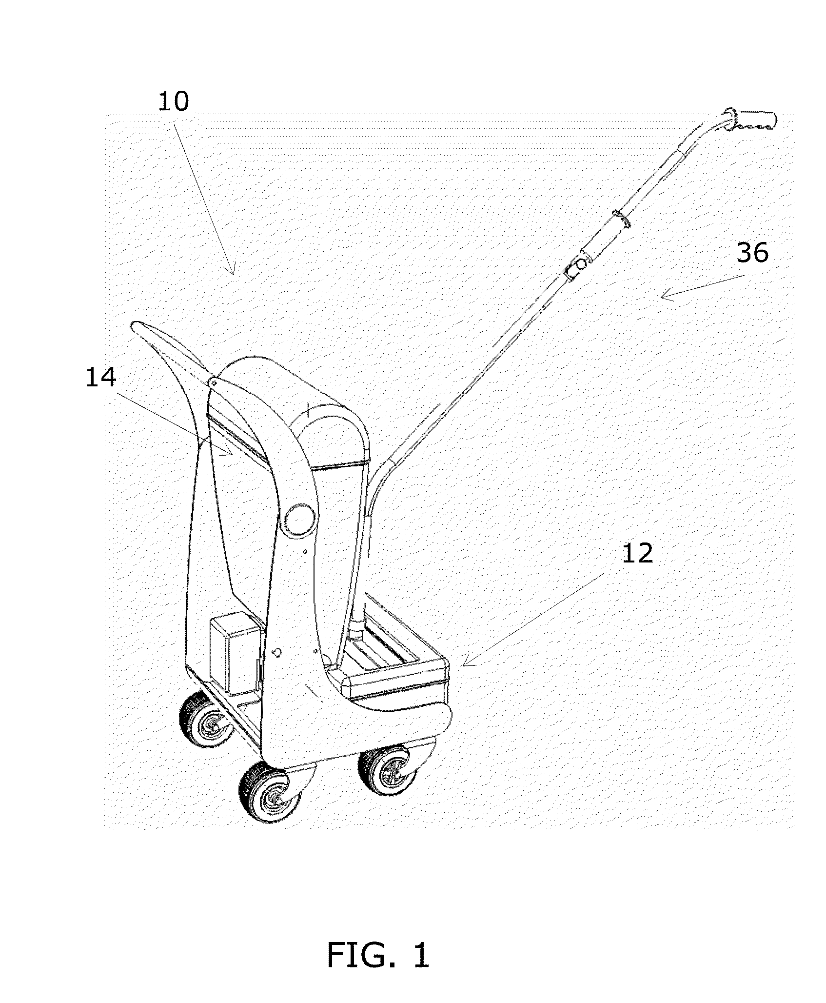
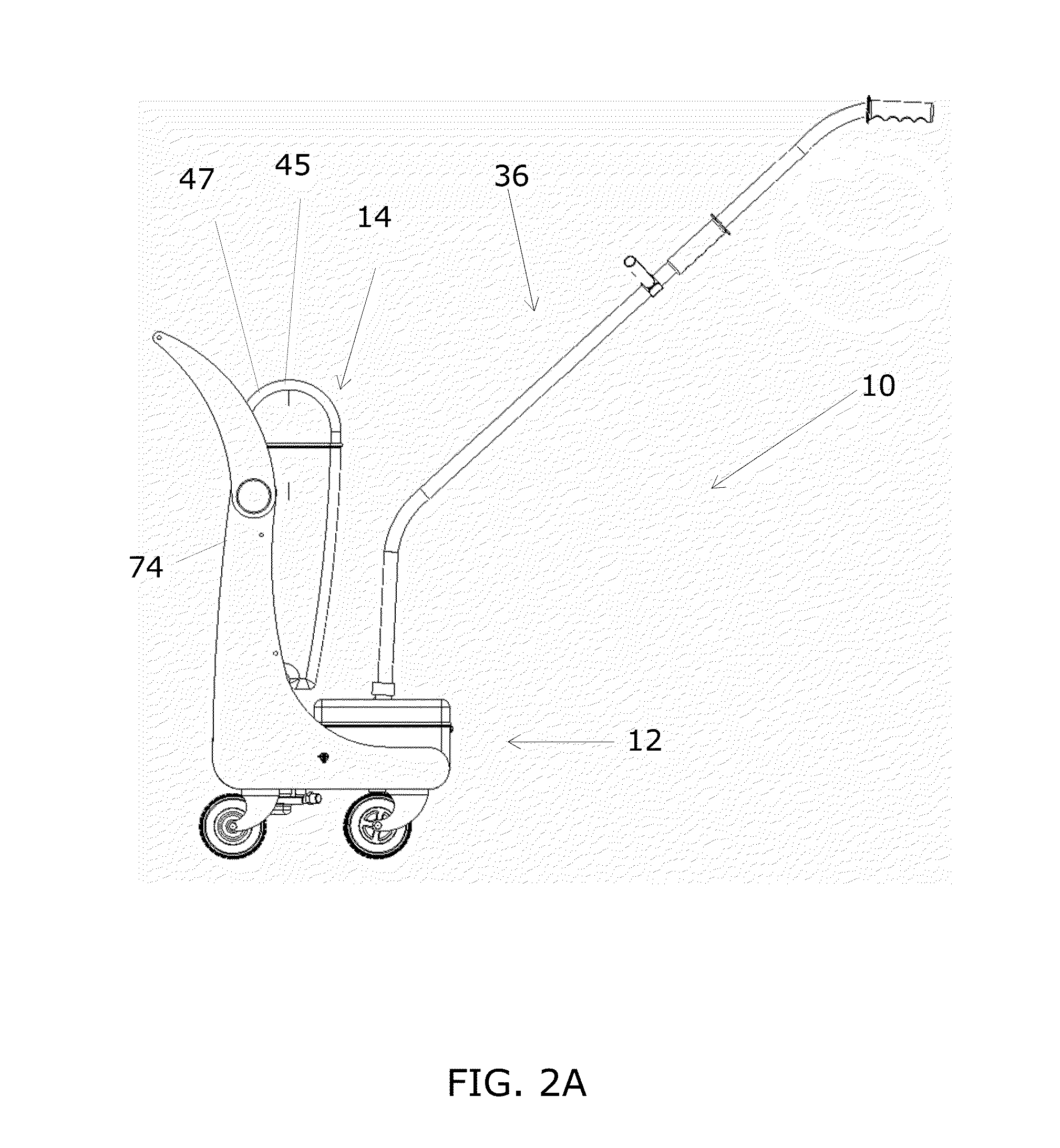
[0044]FIGS. 1, 2A-2D and 3A-3D show multiple embodiments including utilization of the various components. As illustrated in FIGS. 1, and 2A-2D, the touch-less mopping system 10 is comprised of the following primary components: a rinse tank 12 to automatedly cleanse a mop head; a holding tank 14 separated from the rinse tank 12; a cleaning mechanism 80 in fluid communication with the rinse tank 12 and the holding tank 14; one or more sensors in communication with the cleaning mechani...


PUM


Abstract

A user touchless mopping system 10 comprising: a rinse tank 12; a holding tank 14; a cleaning mechanism 36 in fluid communication with the rinse tank and the holding tank; a sensor 39 in communication with the mop and configured for determining that a mop cleaning head has been received in a receptacle 41 of the mopping system; and, a control module 48 configured to direct the cleaning mechanism to clean the mop head when placed into holding tank receptacle and detected by sensors. The holding tank 14 comprises an automated water filtering system configured to provide clean and disinfected water to the mop head; and, the rinse tank 12 comprises an automated touch-less mop head rinsing, wringing mechanism. The system can include suctioning of contaminated water out of the rinse tank, through the holding tank filtering and disinfectant system to recycle the water for later usage.

Description

CROSS-REFERENCE TO RELATED APPLICATIONS[0001]This application claims benefit and priority of co-pending U.S. Provisional Patent Application Ser. No. 61 / 922,243, filed Dec. 31, 2013, the disclosure of which is hereby incorporated by reference in its entirety.FIELD OF THE INVENTION[0002]Disclosed embodiments generally relate to mopping systems for cleaning solid surfaces such as floors.BACKGROUND[0003]There are two primary types of floor cleaning systems: vacuums and mops. Vacuums primarily utilize suction to pull dust and dirt from carpets and floors, while mops have historically comprised wet sponges, or the like, for applying liquids to wipe a floor clean. Conventional mop and bucket systems are not reliable in removing all dirt from a floor due to the tendency of the mop head, be it a sponge or fabric type, to permanently embed dirt and bacteria into the fibers of the mop head that are then re-deposited onto the floor. Every time the user dumps the mop head into the bucket, they a...

Claims


Application Information

Patent Timeline
IPC IPC(8): A47L13/20A47L13/42A47L13/59
CPCA47L13/20A47L13/42A47L13/59A47L13/254
Inventor BRAIN, TERRYANGELOVA, NIKOLETA
Owner PURESSENCE VENTURES
Why Eureka
Try Eureka