Cleaning apparatus for in-vehicle optical sensor

a technology for cleaning apparatus and optical sensor, which is applied in the direction of vehicle cleaning, cleaning using liquids, instruments, etc., can solve the problems of dripping from the lens surface, using cleaning liquid which cleaned the lens surface,

Active Publication Date: 2015-07-02
DENSO CORP
View PDF1 Cites 62 Cited by
  • Summary
  • Abstract
  • Description
  • Claims
  • Application Information

AI Technical Summary

Benefits of technology

[0011]In view of the above, it is an object of the present disclosure to provide an apparatus for cleaning an in-vehicle optical sensor in such a manner that a vehicle body and parts mounted on the vehicle body are less likely to be soiled with a used cleaning liquid.
[0012]According to an aspect of the present disclosure, a cleaning apparatus for an in-vehicle optical sensor includes a cleaning liquid nozzle and an air nozzle. The cleaning liquid nozzle jets out a cleaning liquid toward a lens surface of a lens of the in-vehicle optical sensor or a translucent surface of a translucent cover covering the lens surface when the translucent cover exists. The air nozzle jets out air toward the used cleaning liquid, which was jetted out from the cleaning liquid nozzle and cleaned the lens surface or the translucent surface, to prevent the used cleaning liquid from dropping from the lens surface or the translucent surface on a predetermined position by blowing away the used cleaning liquid.
[0013]Thus, since the used cleaning liquid dripping from the lens surface (or the translucent surface) is blown away by the air and does not drop on the predetermined position, a vehicle body and parts mounted on the vehicle body are less likely to be soiled with the used cleaning liquid.

Problems solved by technology

However, it is unavoidable that a used cleaning liquid which cleaned the lens surface (or the translucent surface) will drip from the lens surface.

Method used


Image

  • Cleaning apparatus for in-vehicle optical sensor
  • Cleaning apparatus for in-vehicle optical sensor
  • Cleaning apparatus for in-vehicle optical sensor

Examples


first embodiment

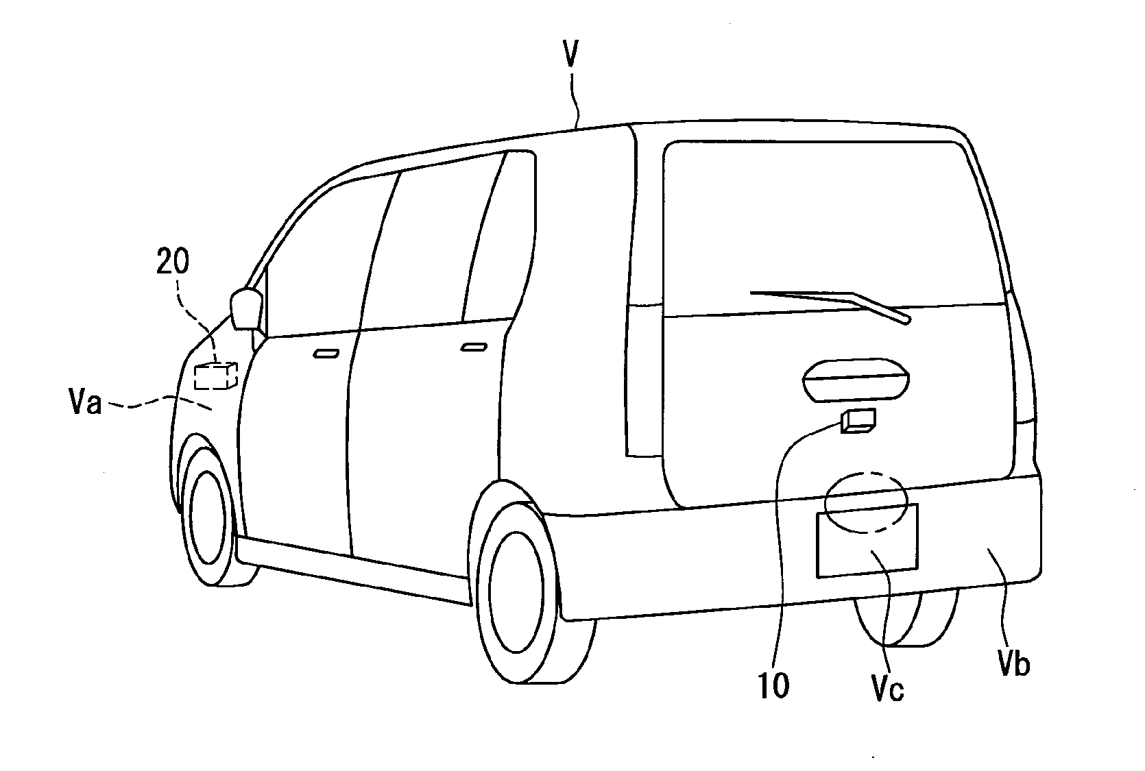
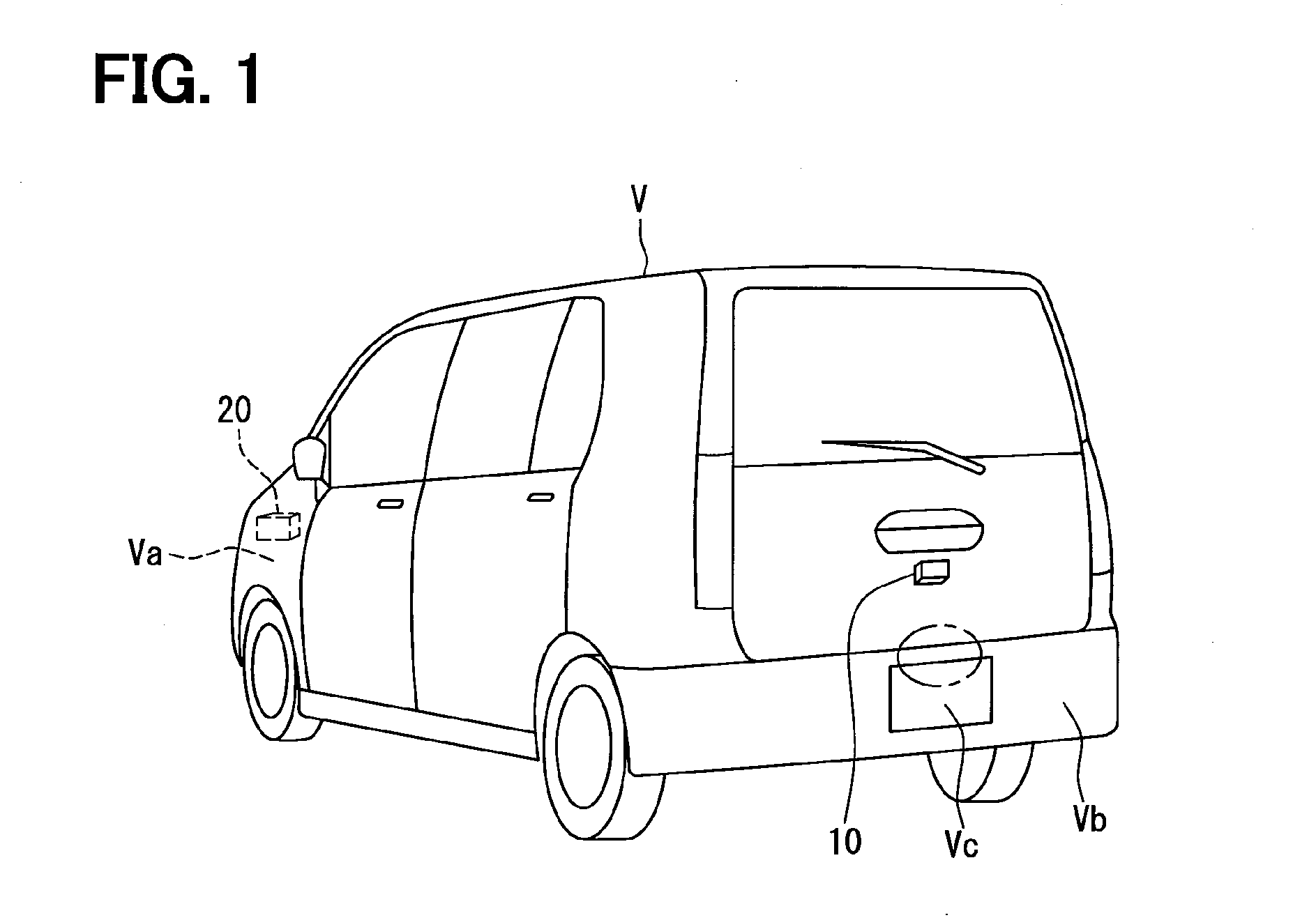
[0028]According to the present embodiment, a camera is taken as an example of an in-vehicle optical sensor to be cleaned, and a camera unit 10 having the camera is mounted at the rear of a vehicle V. An image of the area behind the vehicle captured by the camera unit 10 is shown on a display installed in the interior of the vehicle and used to assist a driver in backing up.

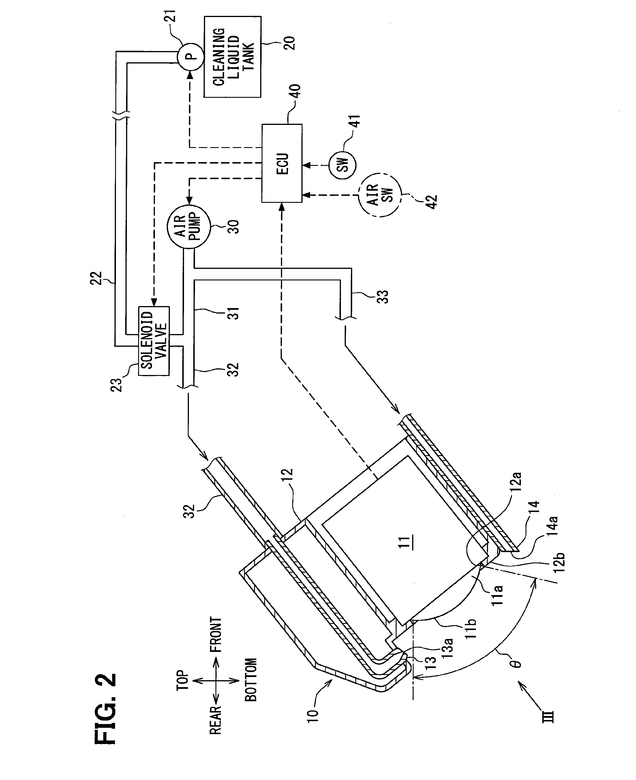
[0029]As shown in FIG. 2, the camera unit 10 includes a housing 12 and a camera 11 held in the housing 12. A lens 11a of the camera 11 is a convex lens and exposed outward from an opening 12a of the housing 12. A portion of the housing 12 forming the opening 12a serves as a lens holder 12b. This lens holder 12b is in contact with the lens 11a and forms a seal which prevents water from entering the housing 12 while fixing the lens surface 11b to a predetermined position.

[0030]The vehicle V is equipped with a cleaning apparatus (a cleaning apparatus for an in-vehicle optical sensor) which cleans a lens surface 11b o...

second embodiment

[0061]In the first embodiment described above, the cleaning liquid nozzle 13 jets out the cleaning liquid together with the air. In contrast, as shown in FIG. 7, according to the present embodiment, the cleaning liquid nozzle 13 jets out only the cleaning liquid without jetting out the air.

[0062]Specifically, instead of the structure shown in FIG. 2 where the branch pipe 33 is connected to the air pipe 31 connected to the air pump 30, an air pipe 35 connected to the air pump 30 is connected to the air nozzle 14.

[0063]The same effects as obtained in the first embodiment can be obtained even in the present embodiment. However, since the force by which the cleaning liquid collides with the lens surface 11b is reduced, the amount of the cleaning liquid necessary to clean up the adhered matters. The structure of the first embodiment is advantageous at this point. However, the present embodiment is advantageous in that the air pipe structure can be simplified by removing the branch pipe 3...

third embodiment

[0065]As shown in FIGS. 8A and 8B, in a camera unit 10A according to the present embodiment, an infrared light 15 (illuminating means) for radiating infrared rays is held in the housing 12 together with a camera 16. The jet pattern S1 of the cleaning liquid jetted out from the cleaning liquid nozzle 13 is set so that it can clean both a lens surface 15a of the infrared light 15 and a lens surface 16a of the camera 16.

[0066]For example, the infrared light 15 is used to supplement the surrounding brightness when the image is captured by the camera 16 at night. Thus, according to the present embodiment, extraneous matters adhered to the lens surface 15a of the infrared light 15 can be suitably removed so that the infrared rays can be radiated suitably. The infrared light 15 can be replaced with a visible-light light (illuminating means).

[0067]The air nozzle 14 described in the first embodiment is included in the present embodiment. Thus, like in the first embodiment, the vehicle V can ...


PUM


Abstract

A cleaning apparatus for an in-vehicle optical sensor includes a cleaning liquid nozzle and an air nozzle. The cleaning liquid nozzle jets out a cleaning liquid toward a lens surface of a lens of the in-vehicle optical sensor or a translucent surface of a translucent cover covering the lens surface when the translucent cover exists. The air nozzle jets out air toward a used cleaning liquid, which was jetted out from the cleaning liquid nozzle and cleaned the lens surface or the translucent surface, to prevent the used cleaning liquid from dropping from the lens surface or the translucent surface on a predetermined position by blowing away the used cleaning liquid.

Description

CROSS REFERENCE TO RELATED APPLICATION[0001]This application is based on Japanese Patent Application No. 2012-162923 filed on Jul. 23, 2012, the contents of which are incorporated herein by reference.TECHNICAL FIELD[0002]The present disclosure relates to a cleaning apparatus for cleaning a lens or a translucent cover of an in-vehicle optical sensor such as a camera or a proximity sensor.BACKGROUND ART[0003]The cleaning apparatus disclosed in, for example, patent literatures 1-5 have a cleaning liquid nozzle for jetting out a cleaning liquid toward a lens surface of a lens (or a translucent surface of a translucent cover). The jetted cleaning liquid removes extraneous matters, such as water and mud, adhered to the lens surface.[0004]The patent literature 5 discloses blowing compressed air to a glass in front of a camera after blowing high-pressure water to it.PRIOR ART LITERATURESPatent Literature[0005]Patent Literature 1: JP-A-2011-240910[0006]Patent Literature 2: JP-A-2011-240912[0...

Claims


Application Information

Patent Timeline
Patent Type & Authority Applications(United States)
IPC IPC(8): B60S1/56B60S1/54
CPCB60S1/54B60S1/56B05B7/0815B08B3/02B60R1/00B60S1/46B60S1/60G02B27/0006
Inventor TANAKA, HITOSHIMATSUMOTO, MUNEAKI
Owner DENSO CORP
Why Eureka
Try Eureka