Solar panel support apparatus

a technology for solar panels and support devices, which is applied in the direction of heat collector mounting/support, light and heating equipment, snap fasteners, etc., can solve the problems of slow and laborious mounting process, inconvenient installation, and high installation costs, and achieves the effect of improving the service life and reducing the cost of installation

Inactive Publication Date: 2015-07-02
RI ENTERPRISES
View PDF13 Cites 22 Cited by
  • Summary
  • Abstract
  • Description
  • Claims
  • Application Information

AI Technical Summary

Problems solved by technology

This mounting process is slow and labor intensive, and thus expensive to install.
Such a technique may not be entirely satisfactory for certain applications, such as high slope structures (e.g., 20 degrees or 30 degrees) as well as locations where there may be high winds or other harsh weather or other conditions.
By undertaking the work from an elevated position in a conventional lift, the installer can fall from the lift and sustain serious injuries.
Also, such an unsafe installation technique which places the installer at risk, may be a violation of governmental safety regulations such as the Occupational Safety and Health Administration federal regulations, and possibly others.
Additionally, in some situations where the malfunctioning solar panel is located in the center of the array of panels, the installer may have to walk on the array of panels in a very unsafe manner to gain access to the panel to be replaced.

Method used


Image

  • Solar panel support apparatus
  • Solar panel support apparatus
  • Solar panel support apparatus

Examples


Embodiment Construction

[0025]Certain embodiments of the present invention will now be described more fully hereinafter with reference to the accompanying drawings, in which some, but not all, embodiments of the invention are shown. Indeed, these embodiments of the invention may be in many different forms and thus the invention should not be construed as limited to the embodiments set forth herein; rather, these embodiments are provided as illustrative examples only so that this disclosure will satisfy applicable legal requirements. Like numbers refer to like elements throughout.

[0026]It will be readily understood that the components of the embodiments as generally described and illustrated in the drawings herein, could be arranged and designed in a wide variety of different configurations. Thus, the following more detailed description of certain ones of the embodiments of the apparatus, system, components and methods of the present invention, as represented in the drawings, is not intended to limit the sc...


PUM


Abstract

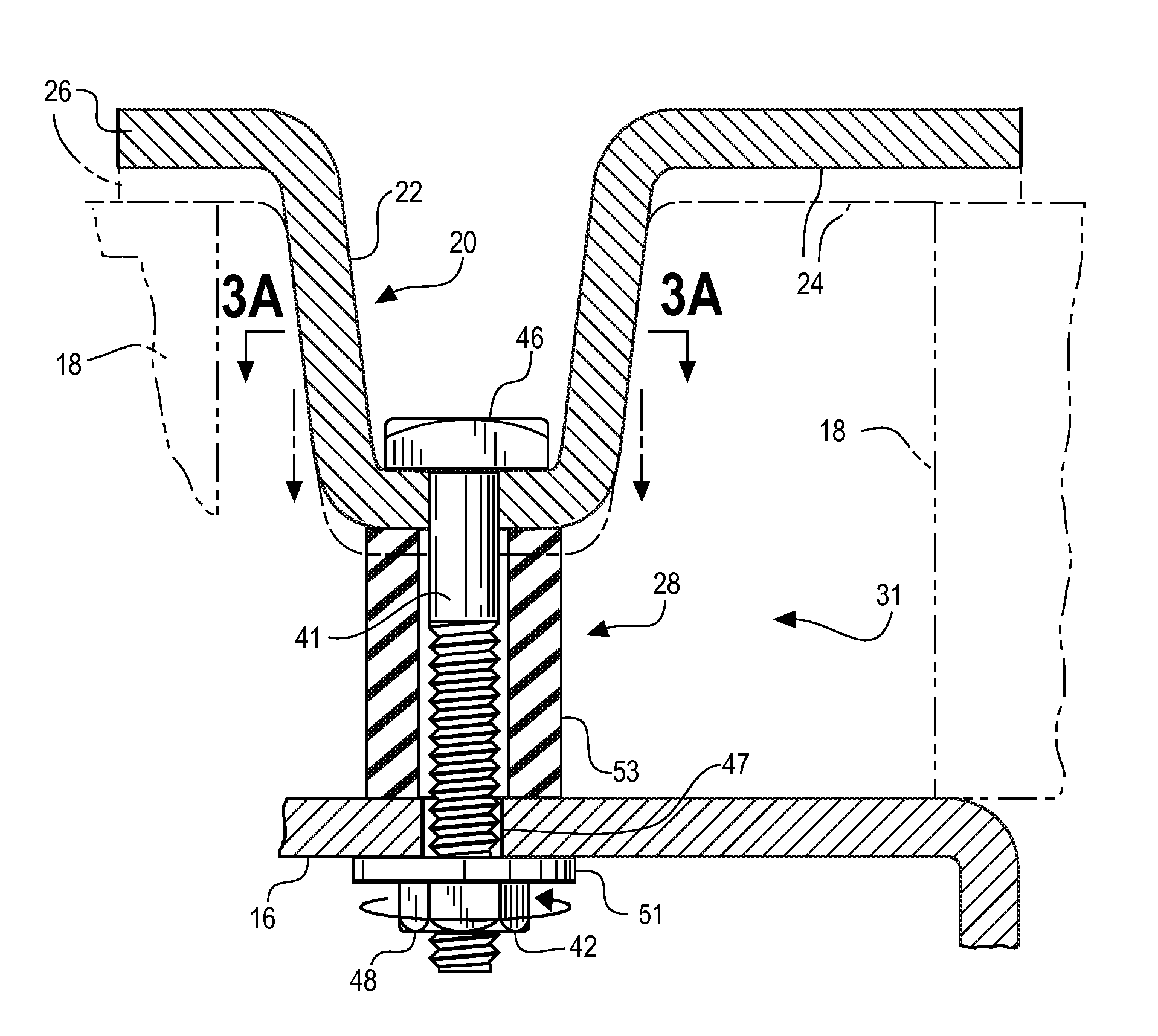
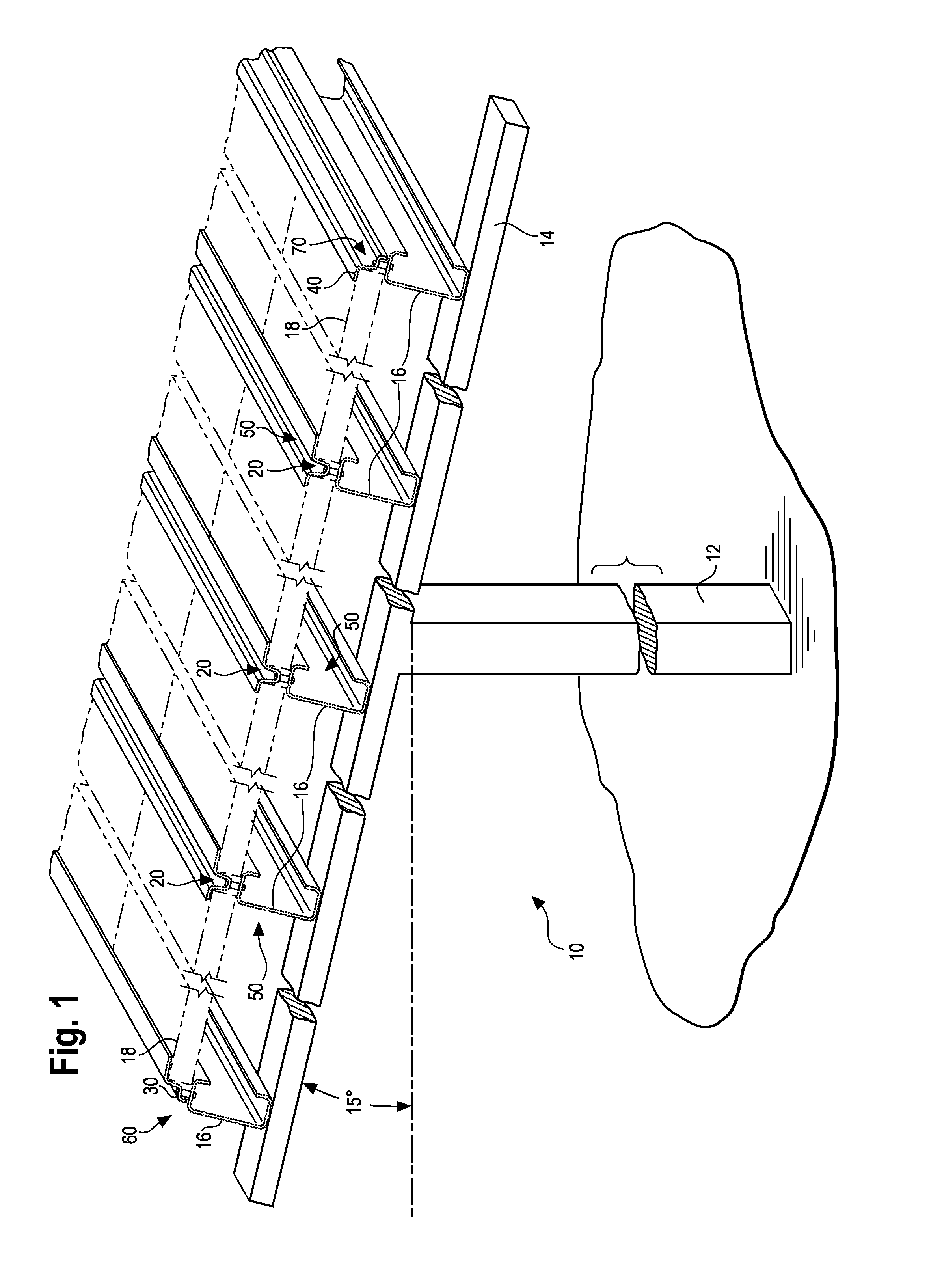
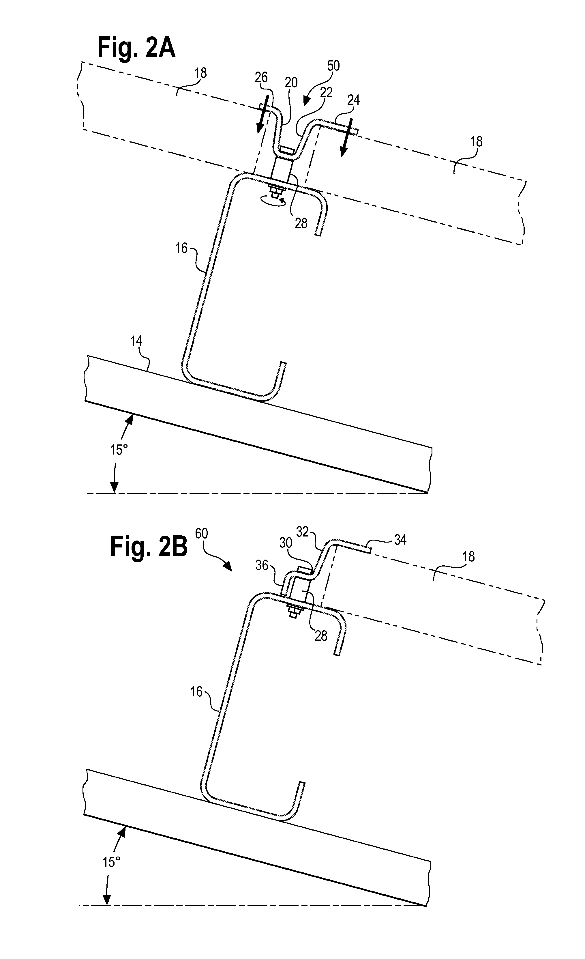
A support apparatus for securing a row of solar panels to a support structure may include a fastener extending between and attaching an elongated clamp rail to a purlin. The fastener has a first non-rotatable end portion. A rotatable member is connected to a second end portion of the fastener for causing, when rotated, the clamp rail to close onto upper marginal edges of the row of solar panels along a continuous line of engagement therewith to help secure the solar panels in place on the purlin.

Description

RELATED APPLICATION[0001]The present patent application is related to U.S. patent application entitled SOLAR PANEL MOUNTING METHODS, filed Jan. 2, 2014, and assigned application Ser. No. ______, which is incorporated herein by reference as if set forth herein in its entirety.FIELD OF THE INVENTION[0002]The present invention relates to a solar panel support apparatus. It more particularly relates to such an apparatus that allows a safer and easier way to mount solar panels in an array in a more secure mannerBACKGROUND ART[0003]This section describes the background art of the disclosed embodiments of the present invention. There is no intention, either express or implied, that the background art discussed in this section legally constitutes prior art.[0004]Solar panel arrays have been constructed by installing them on purlins mounted on top of a foundation system or support structure, which may include a series of posts and other components to support the arrays high off of the ground...

Claims


Application Information

Patent Timeline
Patent Type & Authority Applications(United States)
IPC IPC(8): F24J2/52H01L31/042F16B2/02
CPCF24J2/5243H01L31/0422F16B2/02F16B2/12Y02E10/47H02S20/00F24S2025/804F24S2025/016F24S2025/014F24S25/12F24S25/636Y10T24/44974Y02E10/50
Inventor LIPPERT, LAWRENCE D.IANNI, MICHAEL JASONROSEPINK, DUSTIN K.KRIVOKOPICH, JON E.HART, CHAD S.
Owner RI ENTERPRISES
Why Eureka
Try Eureka