Measuring element, measuring body and measuring arrangement for measuring a force, and use of such a measuring body

a technology of measuring elements and force, applied in the direction of electrical/magnetic measuring arrangements, instruments, using electrical/magnetic means, etc., can solve problems such as systematic measuring errors, and achieve the effects of reducing crosstalk respectively, cost-effectively, and reducing labor intensity

Active Publication Date: 2015-07-02
KISTLER HLDG AG
View PDF12 Cites 6 Cited by
  • Summary
  • Abstract
  • Description
  • Claims
  • Application Information

AI Technical Summary

Benefits of technology

[0011]It is the objective of the present invention to disclose a measuring element of the initially described type, in which crosstalk caused by transverse forces Fxy acting upon the measuring element is reduced without noticeable loss of load carrying capacity. The invention accordingly discloses a measuring body, a measuring arrangement and a use of such a measuring body, in which crosstalk respectively is significantly reduced. The invention also aims to disclose a method for cost-efficiently manufacturing such a measuring element with little effort.

Problems solved by technology

When such a transverse force Fxy occurs, these Fz-measuring elements generate interference signals in that charges are emitted in certain quantities on the surfaces that are in electric contact with the electrodes.
In this way, a systematic measuring error is created.
This results in crystal plates with longitudinal effect that are particularly well suited for measuring forces, which is why they are preferably used in the aforementioned applications, In such measuring elements, however, the aforementioned crosstalk and the associated generation of interference signals occur in the aforementioned applications.

Method used


Image

  • Measuring element, measuring body and measuring arrangement for measuring a force, and use of such a measuring body
  • Measuring element, measuring body and measuring arrangement for measuring a force, and use of such a measuring body
  • Measuring element, measuring body and measuring arrangement for measuring a force, and use of such a measuring body

Examples


Embodiment Construction

[0026]The invention is described in greater detail below with reference to the figures. Identical components / circumstances are respectively identified by the same reference symbols.

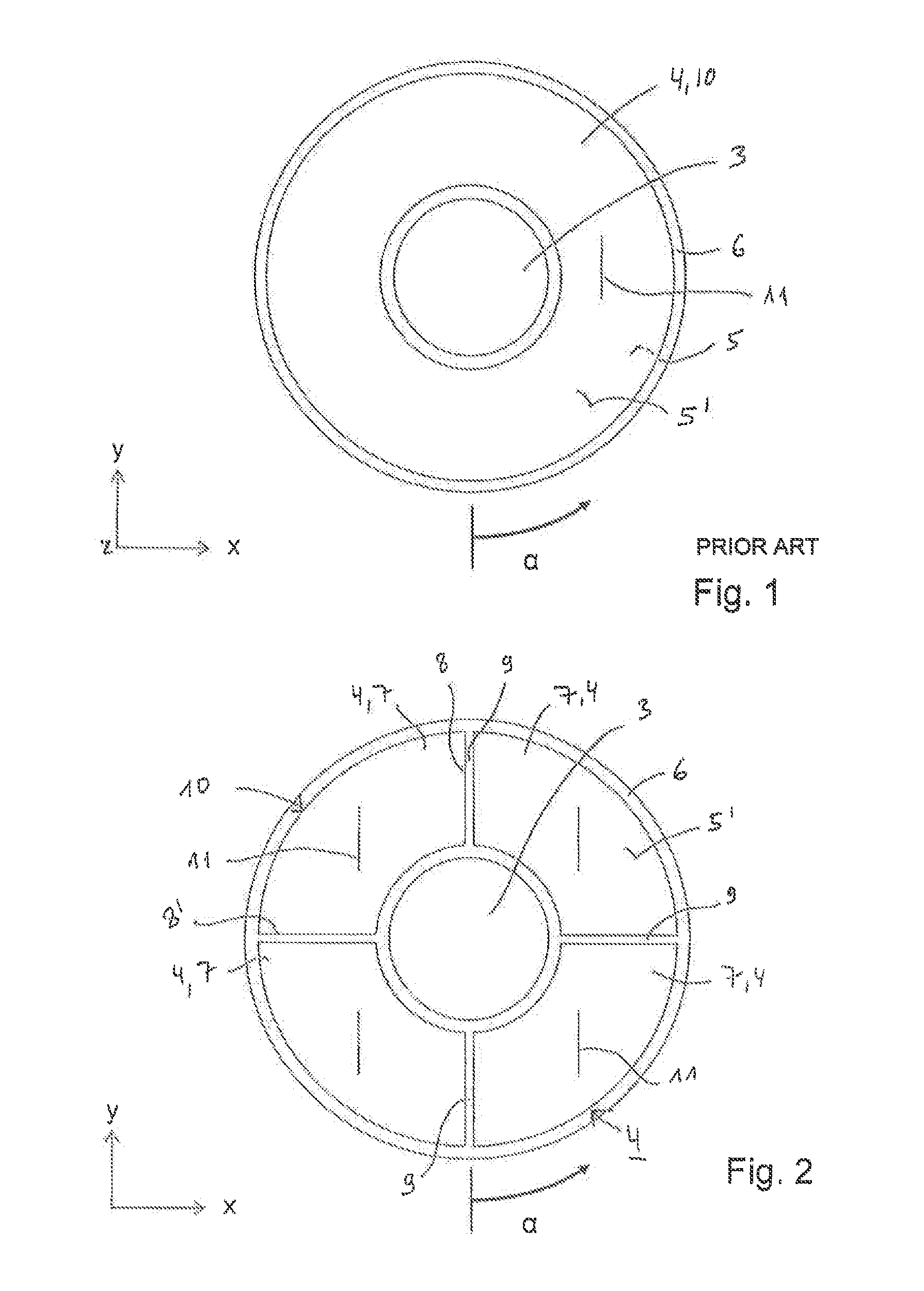
[0027]FIG. 1 shows a one-piece measuring element 4 according to the prior art such as, for example, a piezoelectric measuring element 4 in the form of a disk 10 that is realized in the form of a perforated disk 10 with a central opening 3 in this case. The measuring element 4 is situated on an electrode 6 with its entire lower surface 5 that is not visible in the figure. A not-shown second electrode 6′ is situated on the upper surface 5′ of the measuring element disk 4. The disk 10 extends in the directions x, y and the normal thereto is referred to as z. The crystal orientation 11 of the measuring element 4 is aligned in any direction within the surface x-y, This crystal orientation 11 refers to the cut of the crystal and designates, for example, the orientation Y or Z of the crystal structure, In FIG. 1...


PUM

PropertyMeasurementUnit
forceaaaaaaaaaa
material propertiesaaaaaaaaaa
shapesaaaaaaaaaa

Abstract

A measuring element formed of a piezoelectric crystal of symmetry class 32 for measuring a force Fz, which acts perpendicularly on the plane x-y and causes a charge accumulation on surfaces of the plane x-y, Applications are measurements in which the transverse forces Fxy orthogonal to the force Fz, which generate an error signal at the measuring element, are expected on the measuring body. The measuring element includes at least four identical measuring element segments having straight edges. In the x-y plane the segments are arranged side by side and spaced apart by narrow gaps at the edges. Together, the segments form the shape of a disc or perforated disc for reducing the interference signals caused by the transverse forces Fxy on the measuring element. The crystal orientations in the x-y plane of all segments are oriented in the same direction or orthogonal to each other.

Description

CROSS-REFERENCE TO RELATED APPLICATIONS[0001]This application claims priority to International Application Serial No. PCT / CH2013 / 000108, filed Jun. 20, 2013, which claims priority to Swiss Application No. 00865 / 12 filed Jun. 20, 2012. International Application Serial No. PCT / CH2013 / 000108 is hereby incorporated herein in its entirety for all purposes by this reference.FIELD OF THE INVENTION[0002]The invention pertains to a piezoelectric measuring element made of a crystal of symmetry class 32, particularly of quartz, which is realized flat in a plane x-y and intended for installation into a measuring body for measuring a force Fz that acts perpendicularly upon the plane x-y. Such a force Fz causes a charge accumulation on the surfaces of the measuring element that receive the force and are provided with electrodes. In this respect, the invention only pertains to measuring elements, in which transverse forces Fxy that act orthogonal to the force Fz and generate an error signal at the...

Claims


Application Information

Patent Timeline
Patent Type & Authority Applications(United States)
IPC IPC(8): G01L1/16G01L5/16
CPCG01L5/167G01L1/16
Inventor KOHLER, DENIS
Owner KISTLER HLDG AG
Why Eureka
Try Eureka