
Radio communication system, base station, and cell selection control method

a radio communication system and cell technology, applied in the field of radio communication systems, can solve problems such as the deterioration of the transmission speed of the terminal assigned to the macrocell base station, and achieve the effect of increasing the capacity of the radio communication system

Inactive Publication Date: 2015-07-02
HITACHI LTD
View PDF7 Cites 4 Cited by
  • Summary
  • Abstract
  • Description
  • Claims
  • Application Information

AI Technical Summary

Benefits of technology

The technical effect of this patent is that it proposes a way to increase the capacity of a radio communication system by effectively utilizing a small cell base station. This results in a larger system capacity and better utilization of available resources.

Problems solved by technology

However, for example, as to upstream communication, since the communication of a terminal assigned a small cell base station functions as interference with the communication of a terminal assigned a macrocell base station and therefore the transmission speed of the terminal assigned the macrocell base station may be deteriorated, it is not necessarily related to the increase of the capacity of the whole system to assign multiple terminals to the small cell base station.

Method used


Image

  • Radio communication system, base station, and cell selection control method
  • Radio communication system, base station, and cell selection control method
  • Radio communication system, base station, and cell selection control method

Examples


first embodiment

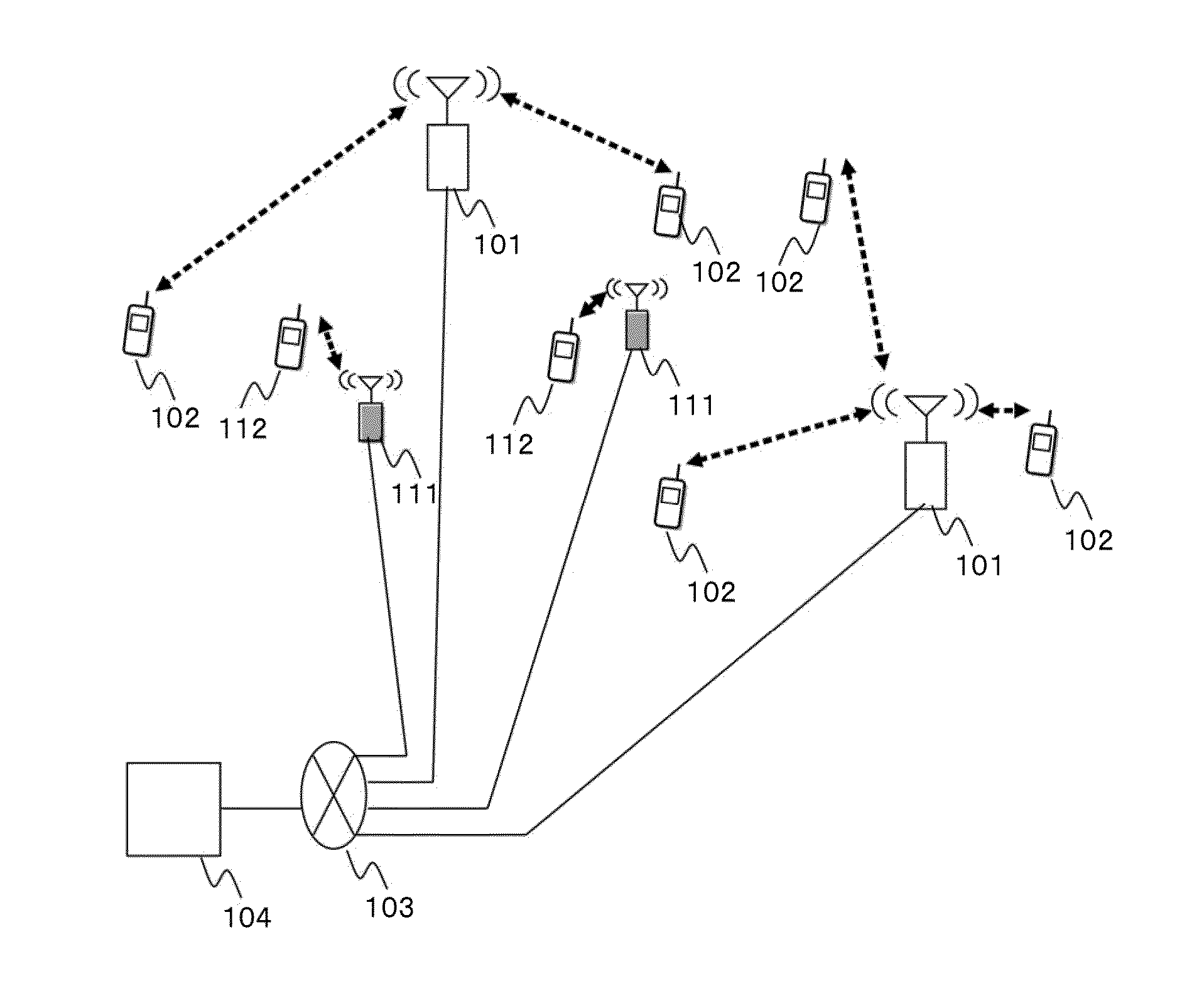
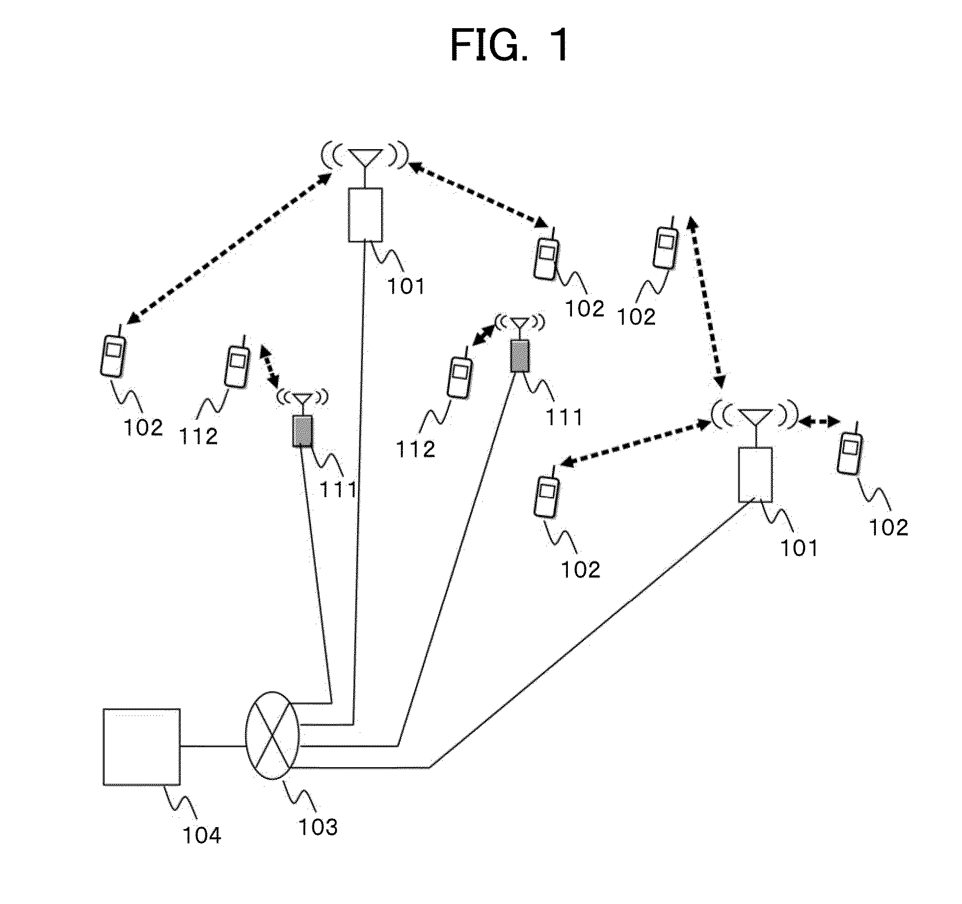
[0025]FIG. 1 shows one example of the configuration of a radio communication system related to all embodiments including a first embodiment. The radio communication system having this configuration is provided with plural macrocell base stations 101, plural small cell base stations 111, plural user terminals 102, 112, a network 103 connected to the plural base stations, and a core network 104 connected to the base stations via the network. In the following description, a signal and communication from the macrocell base station 101 or the small cell base station 111 to the user terminal 102 or 112 are called are called a downlink signal and downlink communication. Conversely, a signal and communication from the user terminal 102 or 112 to the macrocell base station 101 or the small cell base station 111 are called an uplink signal and uplink communication.

[0026]The macrocell base station 101 is connected to the core network 104 via the network 103. The macrocell base station 101 tran...

second embodiment

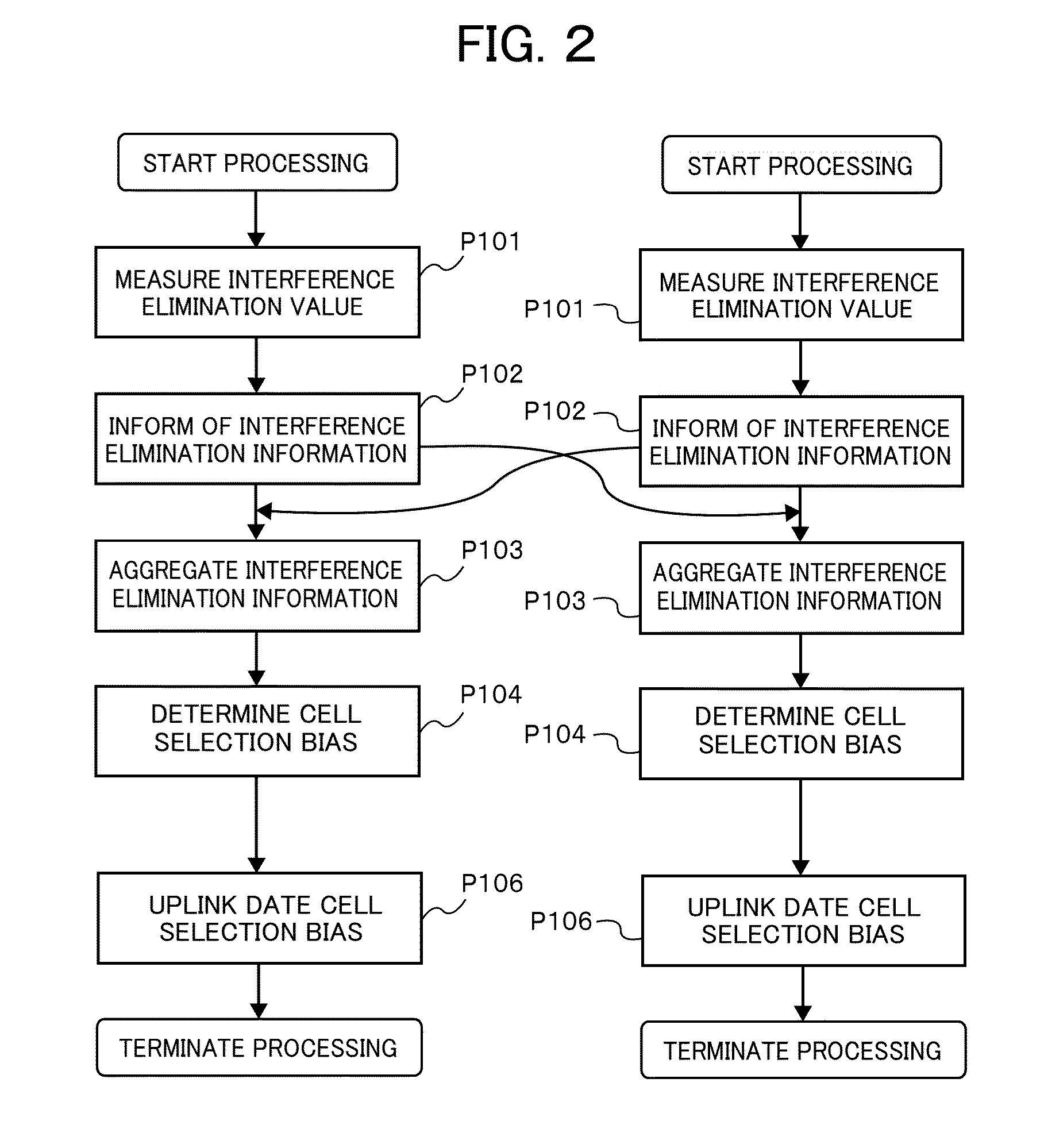
[0057]Next, a second embodiment in which cell selection bias values of plural base stations are collectively determined in a center will be described referring to FIG. 7. FIG. 7 shows a flow of a cell selection bias correcting process in the second embodiment. In the cell selection bias correcting process in the first embodiment, cell selection bias is determined in each base station. However, in the cell selection bias correcting process in this embodiment, cell selection bias values of plural base stations are collectively determined in the center. The cell selection bias correcting process is also executed by a processor described above in a base station.

[0058]In FIG. 7, only one base station of the plural base stations is shown. In the following description, the one base station is described, but the similar processing is respectively executed in the plural base stations. The center in this embodiment may also exist in the core network 104 as shown in FIG. 1 as an independent ce...


PUM


Abstract

The present invention provides a method of controlling the selection of a cell in a radio communication system for increasing the capacity of the system by effectively utilizing a small cell base station and a base station apparatus for realizing it. At least one base station of a macrocell base station and a small cell base station is provided with plural antennas, and the base station selects a cell and adjusts a criterion for reselection by generating processing gain using the plural antennas by signal processing and performing a cell selection bias correcting process using the processing gain using the plural antennas.

Description

FIELD OF THE INVENTION[0001]The present invention relates to a radio communication system, especially relates to technique that controls the selection of a cell in a cellular radio communication system.BACKGROUND OF THE INVENTION[0002]According to the band widening of radio communication, a multicarrier communication mode of dividing transmit information into plural frequency bands called a subcarrier to communicate is used. OFDM (Orthogonal Frequency Division Multiplexing) in the multicarrier communication mode is adopted in various systems because a guard band between subcarriers is made unnecessary by utilizing the orthogonality of a signal, enhancing resistance to a delayed wave by narrowing bandwidth per subcarrier, and the high frequency efficiency can be realized. In addition, OFDMA (Orthogonal Frequency Division Multiple Access) for multiple access by dividing radio resources in the OFDM per unit called a resource block having fixed time length with one or plural subcarriers...

Claims


Application Information

Patent Timeline
IPC IPC(8): H04W48/20
CPCH04W48/20H04W84/045
Inventor TAMAKI, SATOSHIYAMAMOTO, TOMONORIISHIDA, HITOSHITAKEDA, ERIKOONO, GO
Owner HITACHI LTD
Learn More