High performance linear moving coil magnetic drive system

a magnetic drive system, high-performance technology, applied in the direction of transducer details, loudspeaker screens, electrical transducers, etc., can solve the problems of poor performance, limited coil size of approximately six inches, and difficult to overcome in the design, manufacturing and material of loudspeaker, etc., to achieve the effect of enhancing the magnetic interaction

Active Publication Date: 2015-07-09
WALL AUDIO
View PDF7 Cites 18 Cited by
  • Summary
  • Abstract
  • Description
  • Claims
  • Application Information

AI Technical Summary

Benefits of technology

[0011]The loudspeaker may be a planar loudspeaker including include a high performance linear moving coil and stationary magnetic drive design which may solve one or more of the issues with traditional loudspeakers, while contributing new progress in the field of rigid planar diaphragm and electro-magnetic drive technologies. The conductor may be removed from the diaphragm and suspended between bars of magnets which may enable new materials and manufacturing methods to create a planar loudspeaker that achieves new levels of acoustic performance. A driver can be suspended between magnets with minimal or reduced separation as disclosed herein.
[0014]Methods may be provided for selecting the permanent magnet composition and size specification to provide sufficient magnetic flux for driving the linear moving coil. The magnets (e.g., FIG. 1A, item 2) may be positioned in a frame (e.g., FIG. 1A, 1B, 2A, 2B, item 1) that may be metal, plastic, wood, or other material to affix and hold in place strong magnets with minimal spacing between rows of magnets (e.g., FIG. 2A, item 3). A preferable embodiment may include a frame of ferrous metal that can enhance magnet positioning, affixation and the resultant flux field. There may be four rows of magnets, two on one side of a central frame bar, two on the opposing side of the central frame bar (e.g., FIG. 2B, item 2), in a quadrupole arrangement (e.g., FIG. 2B, item 2, showing North and South poling of magnets). The magnets may also be held in place by an adhesive, a flange, metal alloy solder or other technique.
[0016]A high performance linear moving coil (e.g., FIG. 3A, 3B, 4A, 4B) may be mounted to the diaphragm (FIG. 5B) to achieve a determined distance from the magnets. The rows of magnets may produce one or more magnetic fields between them as produced by electrical signals passing through the conductor coil that is attached to the diaphragm. The moving coil may be a racetrack coil constructed of metal traces on printed circuit board (PCB) material such as FR4, flex-circuitry membrane materials, Mylar, or other flexible or semi-rigid materials and may include an electronic device or component, or other electrical connection. In one embodiment, the target resistance value is 8 ohm nominal. An equalizer circuit to tune the voltage at any frequency may be included in another embodiment. In another embodiment, a metallic and / or ferromagnetic finely ground particulate may be applied to enhance the magnetic interaction within the quadrupole magnetic field. The linear moving coil may be enclosed between two unidirectional carbon fiber sheets of fabric, two L-shapes to bring together into a T-shape (e.g., FIG. 4A, 4B), with impregnated material enhancements and final assembly curing steps. One embodiment may position the linear coil between the rows of magnets where it vibrates and levitates according to the electrical current and magnetic flux. The coil may return to its original central neutral position after an internal or external force is applied. The movement can be stabilized in low frequency excitation (fast bass). Other embodiments can optimize the dynamics of the loudspeaker for small size, large commercial use, or small-space acoustic dynamics for specific targets such as auto interior or aircraft speakers.
[0017]The diaphragm (e.g., FIG. 5A, 5B) may include a thin film, a thick film, a man-made material such as Kevlar fiber fabric, unidirectional carbon fiber fabric, a natural material such as cork or Corecork, Dyvincell or Rohacell foam or a combination of layered materials (e.g., FIG. 5A, item 11, 12). The film may be movable in response to the moving coil force created by interaction between the magnetic fields produced by the magnets and the magnetic field produced with the electrical signals. The resulting movement of the film may produce sound. The diaphragm may be surrounded by a frame (e.g., FIG. 6A) with the encapsulated PCB-type coil in the approximate center (e.g., FIG. 6A, item 16) attached to the composite sound panel sub-assembly (e.g., FIG. 6A, item 15) with a rubber foam material (e.g., FIG. 6A, item 17) providing particulate protection for the moving coil and magnet spacing, and resonant stabilization and attachment to the frame.

Problems solved by technology

Several difficulties in loudspeaker design, manufacturing and materials have presented challenges to be overcome.
The limitation of this coil size is approximately six inches due to pre-stress in the wire and an increasingly lower yield and poor performance.
Wire breakage is a problem and the number of “race-track turns” is reported to be about 56 turns before the wire pre-stress makes it impossible to achieve the flatness required for use in proximity to the magnets and within the magnetic flux field required.
Transducers of substantially rigid planar diaphragms present a challenge to current electro-magnetic drive systems and specifically to linear moving coils by presenting a low impedance to the amplifier which reduces high fidelity performance by not driving the transducers properly.
The space limitations and configuration of a wide variety of listening environments have presented a big challenge to past designers of loudspeakers and audio systems to try to create a system and known directivity pattern.
Size and space constraints of a particular environment have made it difficult in the past to achieve the desired performance from traditional audio systems.
Loudspeakers include a frame that supports magnets used to move the coils, the diaphragm and the terminal, consequently, has faced its own design difficulties.
Historically, loudspeaker technology has relied on a single magnet, dual pole drive system, which resulted in a flux field that was non-linear and limited the dynamic response of the speaker.

Method used


Image

  • High performance linear moving coil magnetic drive system
  • High performance linear moving coil magnetic drive system
  • High performance linear moving coil magnetic drive system

Examples


Embodiment Construction

[0042]The invention provides systems and methods for controlling movement of a diaphragm in a loudspeaker in accordance with aspects of the invention. Various aspects of the invention described herein may be applied to any of the particular applications set forth below or for any other types of audio systems. The invention may be applied as a standalone system or method, or as part of an integrated loudspeaker system. It shall be understood that different aspects of the invention can be appreciated individually, collectively, or in combination with each other.

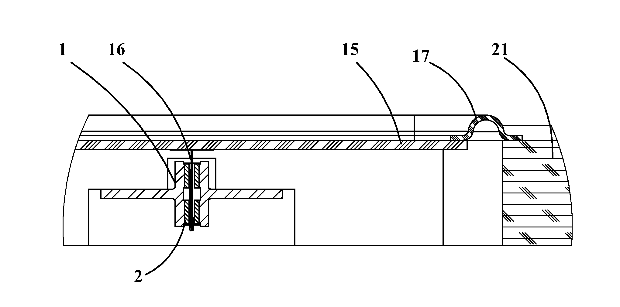
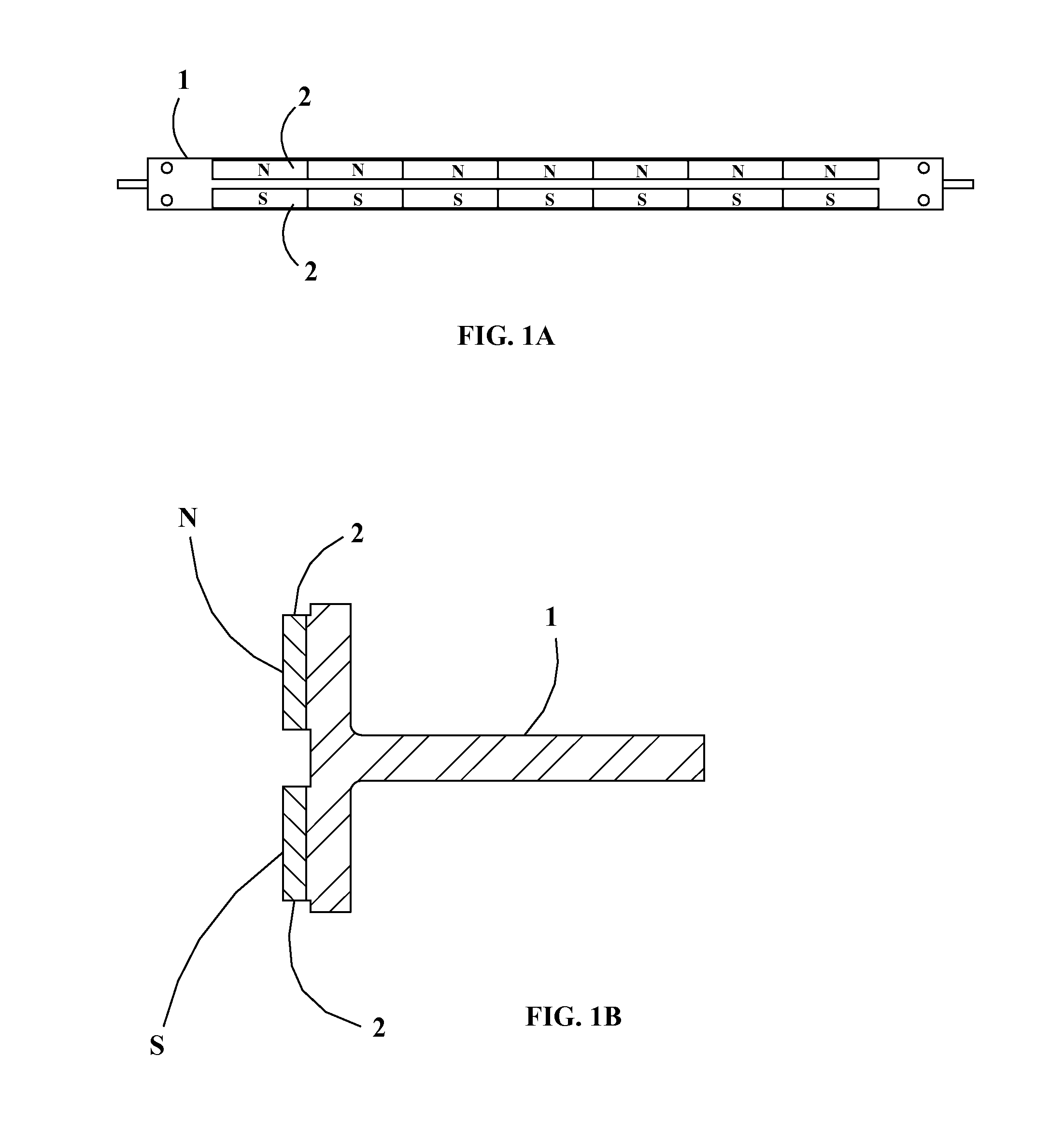
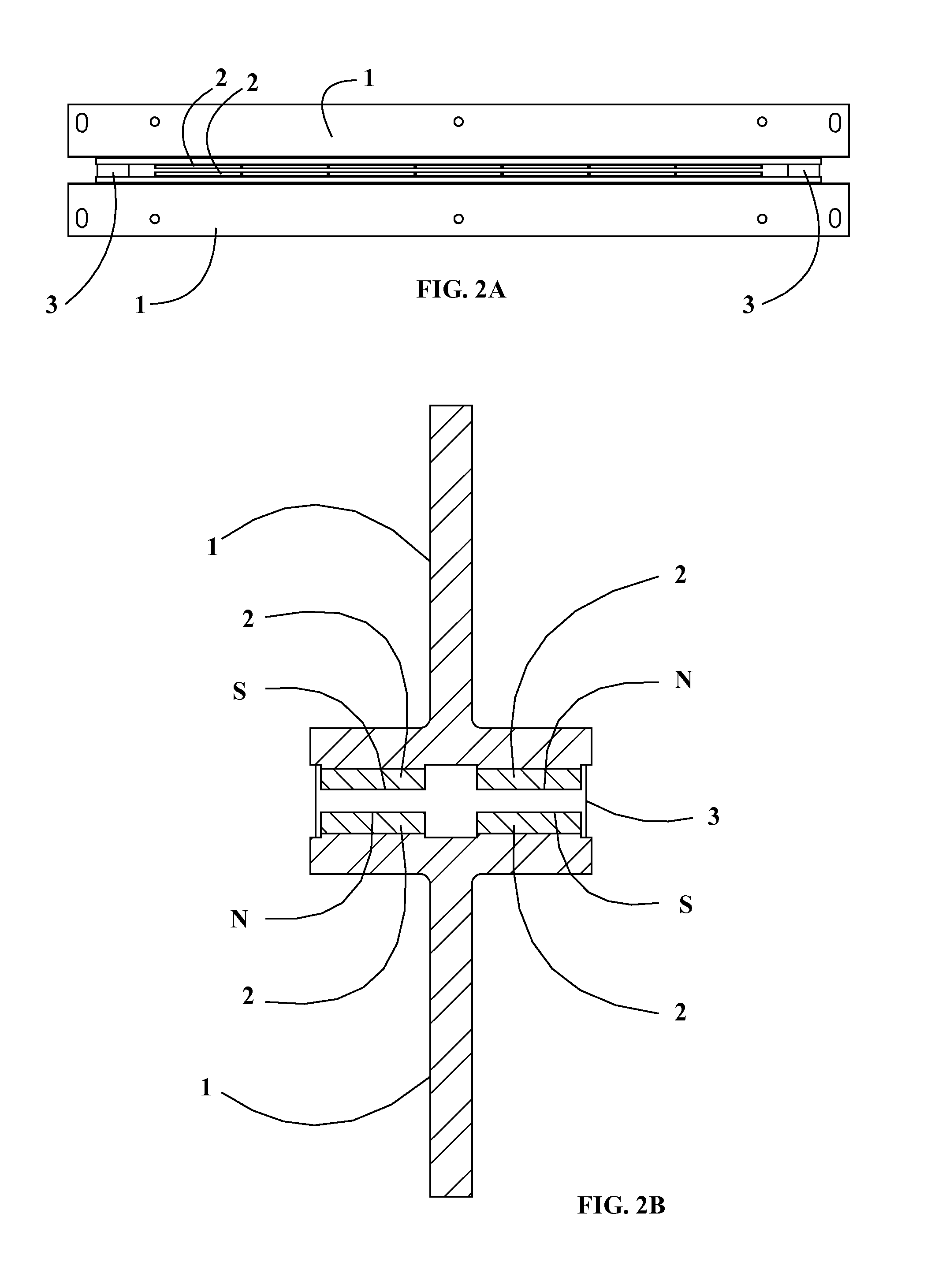
[0043]A loudspeaker may include a diaphragm which may be attached to a frame under tension. Vibration of the diaphragm produces sound from the loudspeaker. A moving coil module may be suspended from the diaphragm and positioned between portions of a magnet assembly. The magnet assembly can create a magnetic field that aids in the control of movement of the moving coil module as current passes through a conductor trace of the mo...


PUM


Abstract

A linear moving coil magnetic drive system includes a continuous loop coil of flat, thin, rigid construction which levitates inside a quadrupole permanent magnet assembly with minimum gap. The linear coil may be a flat, racetrack-shaped, continuous loop, which may be constructed with single or multilayers PCB, flex-circuit, or other membrane process. The linear coil may include a coating of permeable magnetic material along the insulated conductor traces. The linear coil may be sandwiched between carbon fiber fabrics and cured to create a long, flat, thin and perfectly straight, extremely stiff, light-weight, load-bearing tee-shaped structure. This structure is levitated inside a quadrupole permanent magnetic assembly with minimum air gap between the high gauss magnets. In additional to the bare conductor traces inside this coil, also integrated into this PCB structure, is simple second-order equalizer electronic circuitry, comprised of surface-mounted resistors, capacitors, and IC chips. Either a close loop or open loop control may be included to tune the voltage amplitude at the resonance frequency of this magnetic drive system.

Description

CROSS-REFERENCE[0001]This application claims the priority of U.S. Provisional Application Ser. No. 61 / 924,042, filed Jan. 6, 2014, which is incorporated herein by reference in its entirety.BACKGROUND OF THE INVENTION[0002]Loudspeakers' general construction includes a diaphragm, typically a thin film attached to a frame under tension, an electrical circuit, and magnetic sources creating a flux field adjacent to the diaphragm. Electrical current is applied to the circuit, which interacts with the magnets and causes a vibration of the diaphragm, which produces the sound from an electro-dynamic loudspeaker.[0003]Several difficulties in loudspeaker design, manufacturing and materials have presented challenges to be overcome. The diaphragm material and construction needs to achieve an optimum or desired resonance frequency, with minimal or reduced changes in frame attachment or tension occurring during extended operation, while minimizing or reducing any sound distortion, damping or frequ...

Claims


Application Information

Patent Timeline
Patent Type & Authority Applications(United States)
IPC IPC(8): H04R9/02H04R31/00H04R1/00
CPCH04R9/027H04R31/00H04R1/00H04R1/023H04R7/10H04R9/025H04R9/047H04R9/06
Inventor FAN, CHIKO
Owner WALL AUDIO
Why Eureka
Try Eureka