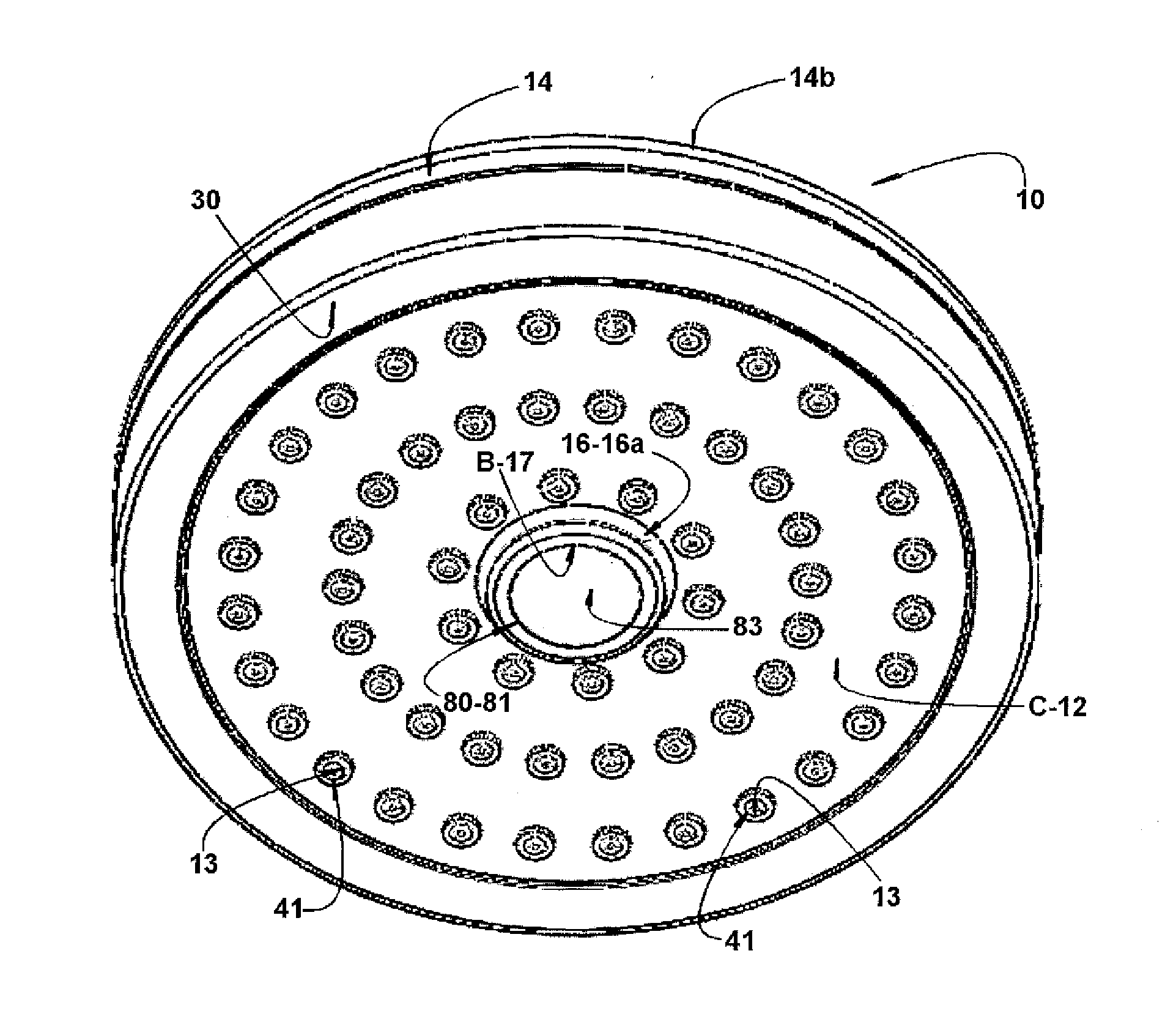
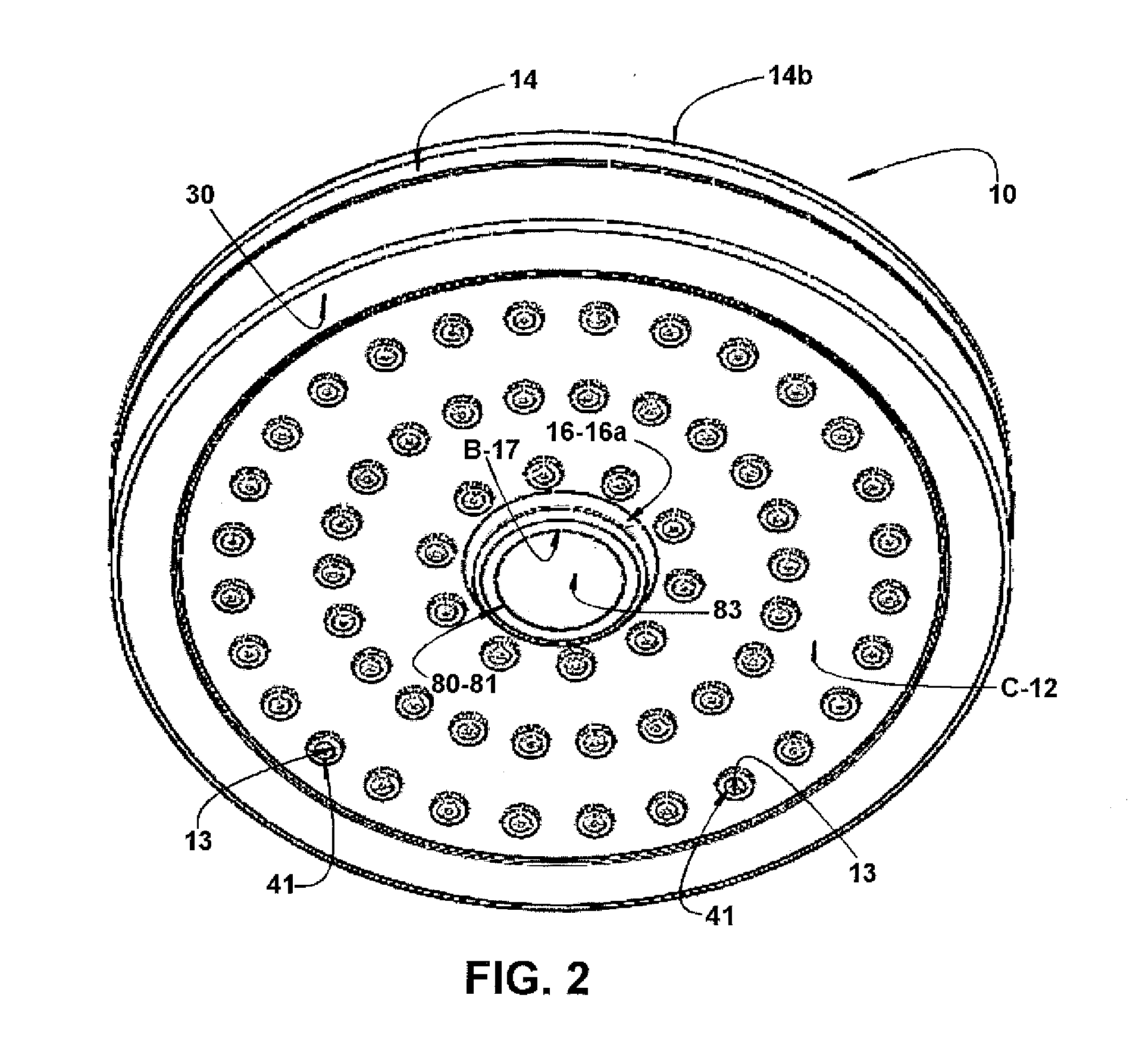
It is well known the problem related to the progressive accumulation of impurities and clogs in the holes of the sieve, which tend to reduce or even block the passage of water through said holes, reducing the amount of water released by the showerhead, compromising its
operational performance and impairing the quality of the bath.
In many known constructions, the operation of cleaning and unclogging the sieve holes requires dismounting the showerhead, said operation being usually complex and time-consuming and effected with the aid of tools and with the showerhead out of operation, that is, it cannot be made during the bath and by means of simple and quick manual actuation of the user.
While allowing for a simple manual operation which can be carried out during the bath, said known solution presents the inconvenience of effecting the cleaning only by the simultaneous introduction of all the pins into the respective holes of the sieve of the showerhead, which holes present a reduced cross section area which becomes easily clogged.
In this situation, dismounting the showerhead is necessary, resulting in the inconveniences of this type of operation.
However, when the showerhead is brought to the on condition, the hydraulic pressure, acting on the sieve, overcomes the resistance imposed by the elastic element, separating the sieve from the cleaning pins and clearing the sieve holes for the
free water discharge upon operation of the showerhead.
Said known construction, although promoting the cleaning of the sieve holes, presents the drawback of maintaining the sieve visually retracted in the interior of the hollow body when the showerhead is in the off condition, making difficult to fully block the water remaining within the hollow body after the user turns off the showerhead after his bath.
After the showerhead is turned off and, particularly, when it is found in an even slightly inclined position, the water retained therewithin cannot drain rapidly, due to the reduced
diameter of the sieve holes, allowing the showerhead to undesirably drip water for a time, even after being taken to the off condition.
Any grain with a larger
diameter will be clogged in one of the sieve holes and will not be removed by the cleaning pin, which may further impair the approximation of the sieve with all the cleaning pins of the inner grid, impeding the automatic cleaning operation to take place and leading to the need of making a troublesome dismounting operation of the sieve for its manual cleaning.
As already mentioned in relation to the other prior art document, grains with larger
diameter tend to be trapped in the sieve holes, and cannot be removed by the cleaning pins, which can impair the approximation of the sieve to the inner cleaning pins, impeding the automatic cleaning function to be carried out and leading to the need of making a laborious disassembly of the sieve for its manual cleaning.
Besides the drawback mentioned above, said second known solution requires the provision of a diaphragm which, in case of undergoing a rupture, even small, will provoke leaks which, depending on the proportions and on the hydraulic supply pressure of the showerhead, may hinder the operation of the latter.
Another limitation, which is inherent to the second previous solution mentioned above, relates to the fact that it does not allow the user to utilize, by means of a simple manual operation during the bath, the pressurized
water flow itself, being admitted in the hollow body of the showerhead, for carrying out an intense cleaning of the sieve holes, with the latter being totally freed from the pins of the cleaning means.

