Thermally stable transparent composite materials

Inactive Publication Date: 2015-07-16
ARMY US SEC THE
View PDF3 Cites 1 Cited by
  • Summary
  • Abstract
  • Description
  • Claims
  • Application Information

AI Technical Summary

Benefits of technology

The invention relates to a composite material made by reinforcing a matrix with filaments. In this embodiment, a third, optional constituent surrounds the reinforcement phase to reduce any mismatch between the wrapping material and the reinforcement or matrix constituents, resulting in a more transparent material.

Problems solved by technology

Composites are not suitable for these applications since they are not typically transparent.
Rather, most conventional composite constituents, such as carbon fibers and aramid fibers, are highly absorbent of visible light or scatter visible light over much of the visible light spectrum and, therefore, cannot be used directly to create transparent composites.
Other materials, such as amorphous or nanocrystalline polymers and glass fibers, can be visually transparent but have a limited physical transparency due to the presence of voids and other impurities that absorb and / or scatter visible light.
Finally, even when two perfectly transparent materials are combined into a composite, if their spectral refractive indices are not identical, then refraction, reflection and scattering effects lead to an unacceptable loss in visible clarity.
However, while these approaches typically yield materials with high transparency, they do not have the mechanical properties necessary for many ballistics and blast applications because the reinforcement is either discontinuous or of low volume fraction and / or randomly oriented.
However, a serious limitation of the index matching approach arises from the temperature dependence of the refractive index known as the thermo-optic coefficient, dn / dT, where n and T are the refractive index and temperature, respectively.
Since transparency requires that the constituent indices be matched to approximately 0.001, the polymer's thermo-optic coefficient leads to a significant refractive index mismatch after a relatively minor, e.g. 10 degrees C., temperature change.
As a result, composite transmissivity tends to be highly temperature dependent with high transparency only possible within a narrow window of temperature.
Since military equipment must be capable of satisfactory operation over a wide temperature range, such loss in transparency is unacceptable.
However, ribbon reinforcement reduces, but does not eliminate, the temperature dependent transmission.

Method used


Image

  • Thermally stable transparent composite materials
  • Thermally stable transparent composite materials
  • Thermally stable transparent composite materials

Examples


Embodiment Construction

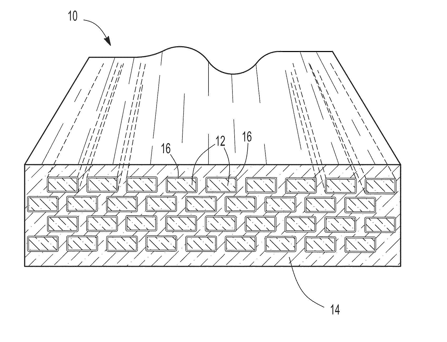
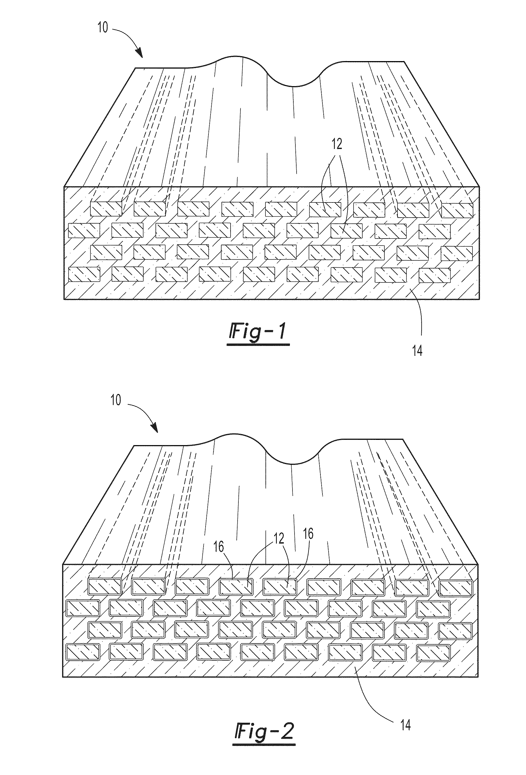
[0024]With reference first to FIG. 1, an example of a composite material 10 according to the present invention is shown. The composite material 10 includes both a reinforcement constituent 12 which is encased within a matrix constituent 14. Preferably, both the reinforcement constituent 12 as well as the matrix constituent 14 are made of a polymer although, alternatively, ceramics, glass, or even an open-cell foam may be used. Suggested matrix polymeric materials include, but are not limited to, epoxies, polyesters such as polymethyl methacrylate (PMMA) and polycarbonate (PC), and polyamides or nylons.

[0025]The reinforcement fibers 12 are illustrated in FIG. 1 as aligned with each other in a set direction. However, such alignment of the reinforcement constituent 12 is not required. Instead, the reinforcement constituent 12 may extend, if desired, in random directions or be woven into a 2- or 3-dimensional fabric.

[0026]Both the reinforcement constituent 12 as well as the matrix const...


PUM

PropertyMeasurementUnit
Lengthaaaaaaaaaa
Lengthaaaaaaaaaa
Lengthaaaaaaaaaa

Abstract

A composite material having a transparent reinforcement constituent encased in a transparent matrix constituent is described and illustrated herein. The reinforcement constituent and matrix constituent are selected so that a difference of the refractive index between the two constituents is less than 0.003 for visible light and across a temperature range of at least 0 degrees centigrade to 50 degrees centigrade.

Description

CROSS-REFERENCE TO RELATED APPLICATIONS[0001]This application claims priority of U.S. Provisional Application No. 61 / 889,595 filed Oct. 11, 2013, the contents of which are incorporated herein by reference.GOVERNMENT INTEREST[0002]The invention described herein may be manufactured, used, and licensed by or for the United States Government.BACKGROUND OF THE INVENTION[0003]I. Field of the Invention[0004]The present invention relates generally to composite materials and, more particularly, to a transparent composite material.[0005]II. Description of Related Art[0006]Continuous fiber reinforced polymer matrix composite materials have emerged as a mass efficient protection material for a range of ballistic and blast applications. Compared to monolithic materials, composite materials provide a unique combination of high fracture toughness and low density.[0007]This reinforcement in properties is due, in large part, to the use of high performance fibers, such as S-glass, carbon, and aramid....

Claims


Application Information

Patent Timeline
IPC IPC(8): C08L77/00C08L23/12C08L33/00C08L63/00
CPCC08L77/00C08L63/00C08L23/12C08L2205/16C08L2201/10C08L2205/03C08L33/00C08L33/12C09D123/0876C08L23/0876Y10T428/249921
Inventor O'BRIEN, DANIEL J.WETZEL, ERIC D.
Owner ARMY US SEC THE
Why Eureka
Try Eureka