Zoom lens and imaging apparatus

a technology applied in the field of zoom lens and imaging apparatus, can solve the problem of unsuitable zoom lens, and achieve the effect of convenient image and compact configuration

Inactive Publication Date: 2015-07-16
FUJIFILM CORP
View PDF1 Cites 5 Cited by
  • Summary
  • Abstract
  • Description
  • Claims
  • Application Information

AI Technical Summary

Benefits of technology

[0008]The present invention has been developed in view of the above circumstances, and it is an object of the present invention to provide a zoom lens capable of securing both a high zoom ratio of approximately 20× and sufficient amount of back focus, and to provide an imaging apparatus equipped with such a zoom lens.
[0038]The zoom lens of the present invention consists essentially of a first lens group having a positive refractive power; a second lens group having a negative refractive power; an aperture stop; a third lens group; a fourth lens group having a positive refractive power; and a fifth lens group in this order from the object side along the optical axis Z. Further, in the zoom lens of the present invention, the first, third, and fifth lens groups are fixed while the second and the fourth lens groups move when changing magnification from the wide angle end to the telephoto end, and focusing is performed by the fourth lens group moving. This facilitates attaining AF (autofocus) and enables a configuration in which the total length is fixed even in the case that the magnification ratio is set to be greater.
[0039]Further, as the fifth lens group consists only of a single cemented lens and has a meniscus shape with a convex surface toward the image side as a whole, the outer diameters of the lenses in the fourth lens group which is a focusing group can be suppressed to reduce the weight thereof. This makes it easy to design a driving system for focusing.
[0040]Further, in the cemented lens above, the refractive index of the medium which constitutes the concave-surface-side lens of the joint surface is configured to be greater than that of the medium which constitutes the convex-surface-side lens. Thereby, the joint surface of the cemented lens operates to diffuse the axial luminous flux. This will be advantageous from the viewpoint of correcting spherical aberration.
[0041]Further, the zoom lens of the present invention is configured to satisfy conditional formulas (1) and (2):0.05<Y / Bf<0.20  (1)1.8<Lsr / Bf<3.5  (2), whereY: the maximum image height,Bf: the air equivalent back focus, andLsr: the distance along the optical axis from the aperture stop to the peak of the most-image-side lens surface.This avoids an increase in the size, enables an appropriate amount of back focus to be secured and the fluctuations in chromatic aberrations to be reduced. Note that the reason therefor will be described in detail in accordance with the embodiments later.
[0042]An imaging apparatus of the present invention is provided with the zoom lens of the present invention. Therefore, a compact configuration can be attained and favorable images can be obtained.

Problems solved by technology

Further, the zoom lens disclosed in Patent Document 2 has a short back focus so that the zoom lens is not suitable for the imaging apparatuses that utilize a color separation prism, for example.

Method used


Image

  • Zoom lens and imaging apparatus
  • Zoom lens and imaging apparatus
  • Zoom lens and imaging apparatus

Examples


example 1

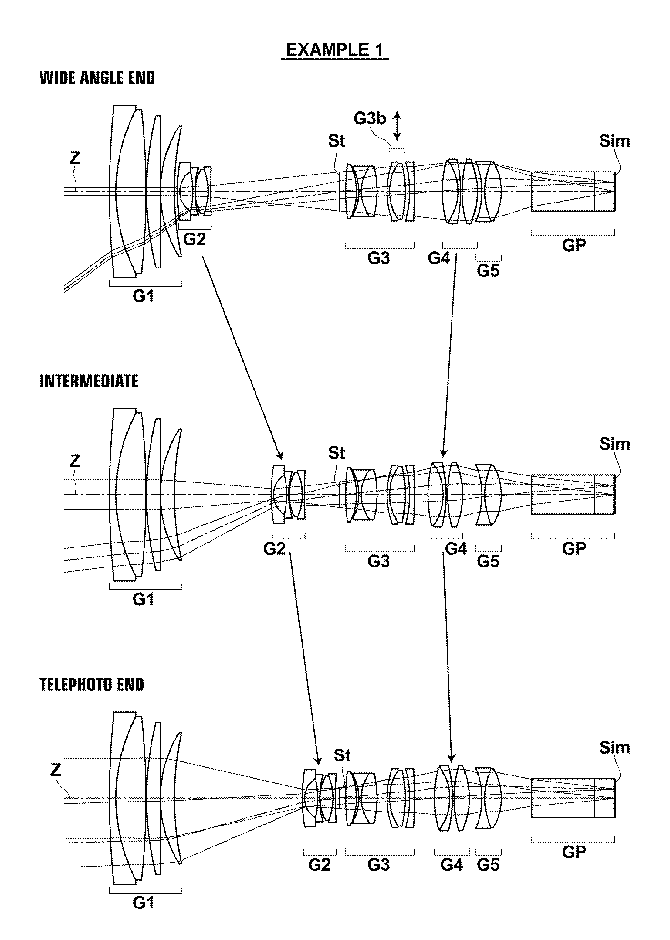
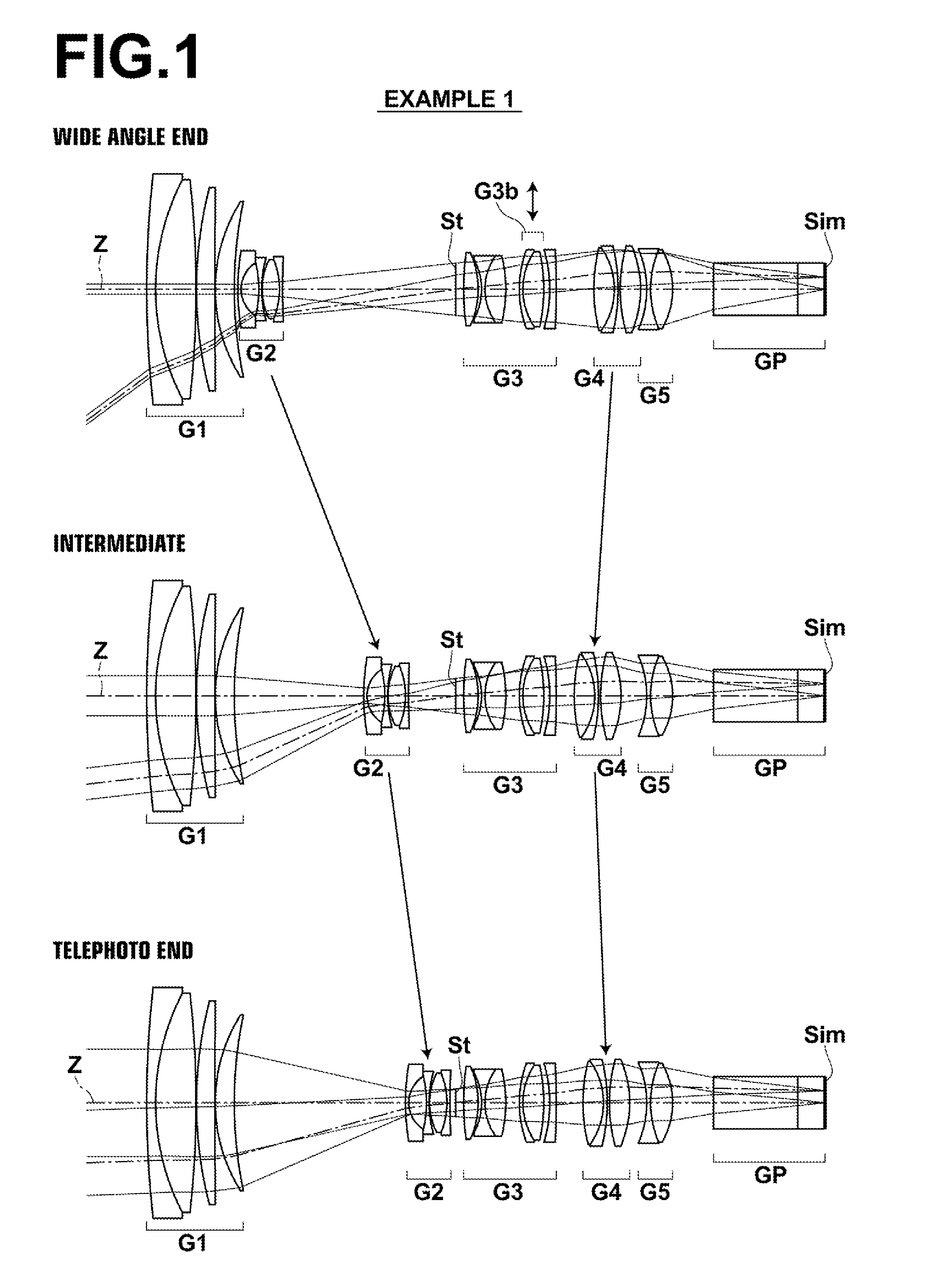
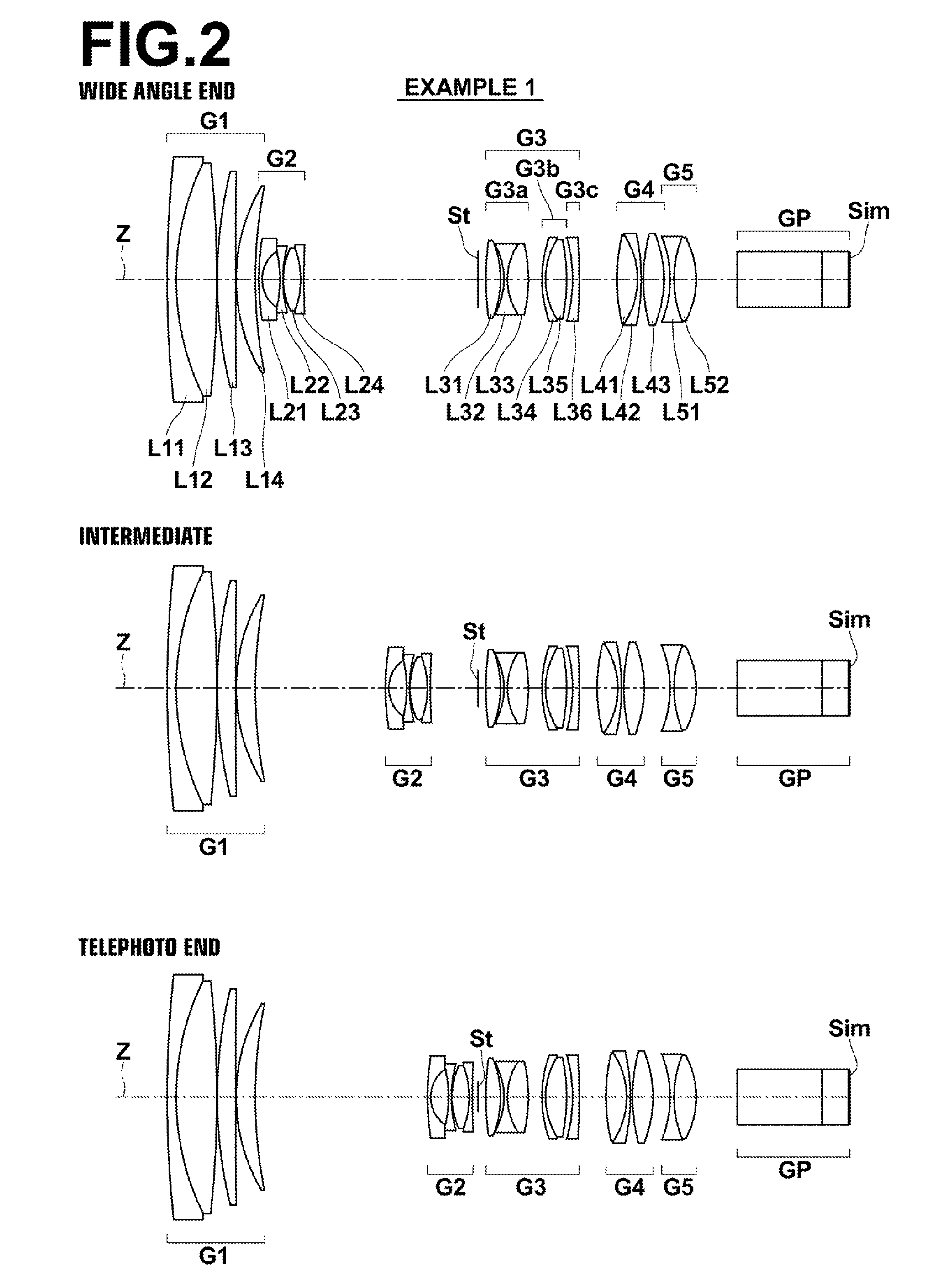
[0091]FIG. 2 shows a cross-sectional view illustrating the lens configuration of an imaging lens of Example 1. In this FIG. 2, the upper stage, the middle stage, and the lower stage respectively shows the arrangement and configuration of each lens group in the wide angle end, those in the intermediate position (the intermediate focal length position), and those in the telephoto end. In FIG. 2, the left side is the object side, and the right side is the image side. Further, the state in which the zoom lens is focused on the object at infinity is shown. FIG. 2 also shows the example in which the optical member GP as described above is disposed between the lens system and the imaging plane Sim.

[0092]The schematic configuration of the zoom lens in Example 1 is as described below. This zoom lens is constituted by a first lens group G1 having a positive refractive power, a second lens group G2 having a negative refractive power, an aperture stop St, a third lens group G3, a fourth lens gr...

example 2

[0116]The lens configuration of the zoom lens of Example 2 is shown in FIG. 3. The schematic configuration of the zoom lens of Example 2 is substantially the same as that of the zoom lens of Example 1 described above.

[0117]Tables 4, 5 and 6 respectively show basic lens data, data related to specs and changes in magnification / focusing, and aspherical surface coefficients of the zoom lens of Example 2. FIG. 9 shows the respective aberration diagrams of the zoom lens of Example 2.

TABLE 4Example 2 / Lens DataSiRiDindjνdj(Surface(Radii of(Distances Between(Refractive(AbbeNumbers)Curvature)Surfaces)Indices)Numbers)156.84390.521.8051825.42213.96382.401.4970081.543−61.90070.02423.13161.011.4970081.545238.12870.02610.10211.101.8040046.58727.3592DD[7] 814.27960.191.8830040.7691.89111.0210−7.14470.171.8830040.76116.82410.02123.87680.981.8466123.7813−5.21510.181.8348142.7314126.2615DD[14]15(Stop)∞0.47*1638.26240.771.5831359.46*17−6.19290.2118−3.64580.201.8450143.50194.04351.101.8150724.2520−9.646...

example 3

[0118]FIG. 4 shows the lens configuration of the zoom lens of Example 3. The schematic configuration of the zoom lens of Example 3 is substantially the same as that of the zoom lens of Example 1 described above, but differs in the configuration of the third-a lens group G3a. That is, in the zoom lens of Example 1, the 32 lens L32 and the 33 lens L33 in the third-a lens group G3a are cemented to each other and both surfaces of the 31 lens L31 are aspherical surfaces, whereas in the zoom lens of Example 3, the 31 lens L31 and the 32 lens L32 are cemented to each other and both surfaces of the 33 lens L33 are aspherical surfaces.

[0119]In the zoom lens of Example 3 as well, the 31 lens L31 and the 32 lens L32 are cemented to each other. Accordingly, the joint surface formed thereby enables longitudinal chromatic aberration to be corrected.

[0120]Tables 7, 8 and 9 respectively show basic lens data, data related to specs and changes in magnification / focusing, and aspherical surface coeffic...


PUM


Abstract

The zoom lens consists essentially of a positive first lens group, a negative second lens group, an aperture stop, a third lens group, a positive fourth lens group and a fifth lens group in this order from the object side. The first, third, and fifth lens groups are fixed while the second and the fourth lens groups move when changing magnification from the wide angle end to the telephoto end, and the fourth lens group moves when focusing is performed. The fifth lens group consists essentially only of a single cemented lens having a meniscus shape with a convex surface toward the image side, and conditional formulas (1), (2) are satisfied when the maximum image height is Y, the air equivalent back focus is Bf and the distance along the optical axis from the aperture stop to the peak of the most-image-side lens surface is Lsr:0.05<Y / Bf<0.20  (1)1.8<Lsr / Bf<3.5  (2).

Description

CROSS-REFERENCE TO RELATED APPLICATIONS[0001]The present application claims priorities under 35 U.S.C. §119 to Japanese Patent Application No. 2014-005650, filed on Jan. 16, 2014 and Japanese Patent Application No. 2014-184967, filed on Sep. 11, 2014. Each of the above application(s) is hereby expressly incorporated by reference, in its entirety, into the present application.BACKGROUND OF THE INVENTION[0002]1. Field of the Invention[0003]The present invention relates to a zoom lens and an imaging apparatus, and more particularly to a zoom lens that can be used for an electronic camera such as a digital camera, a video camera, a broadcasting camera, a movie camera, a surveillance camera, and the like as well as an imaging apparatus mounted with this zoom lens.[0004]2. Description of the Related Art[0005]Conventionally, zoom lenses, which consist of a first lens group having a positive refractive power, a second lens group having a negative refractive power, a third lens group having ...

Claims


Application Information

Patent Timeline
Patent Type & Authority Applications(United States)
IPC IPC(8): G02B15/167G02B27/64
CPCG02B27/646G02B15/167G02B15/1451G02B15/17
Inventor KAWANA, MASANAO
Owner FUJIFILM CORP
Why Eureka
Try Eureka