Electric vehicle and control method of electric vehicle

a technology of electric vehicles and control methods, applied in the direction of motor/generator/converter stoppers, battery/fuel cell control arrangements, dynamo-electric converter control, etc., can solve the problem of lowering the driving comfort and improve the driving comfor

Active Publication Date: 2015-07-16
TOYOTA JIDOSHA KK
View PDF10 Cites 13 Cited by
  • Summary
  • Abstract
  • Description
  • Claims
  • Application Information

AI Technical Summary

Benefits of technology

[0015]The present invention achieves an advantage that drivability is improved by restricting the frequency of sw

Problems solved by technology

It has been a problem that drivability is lowered due to occurrence of torque

Method used


Image

  • Electric vehicle and control method of electric vehicle
  • Electric vehicle and control method of electric vehicle
  • Electric vehicle and control method of electric vehicle

Examples


Embodiment Construction

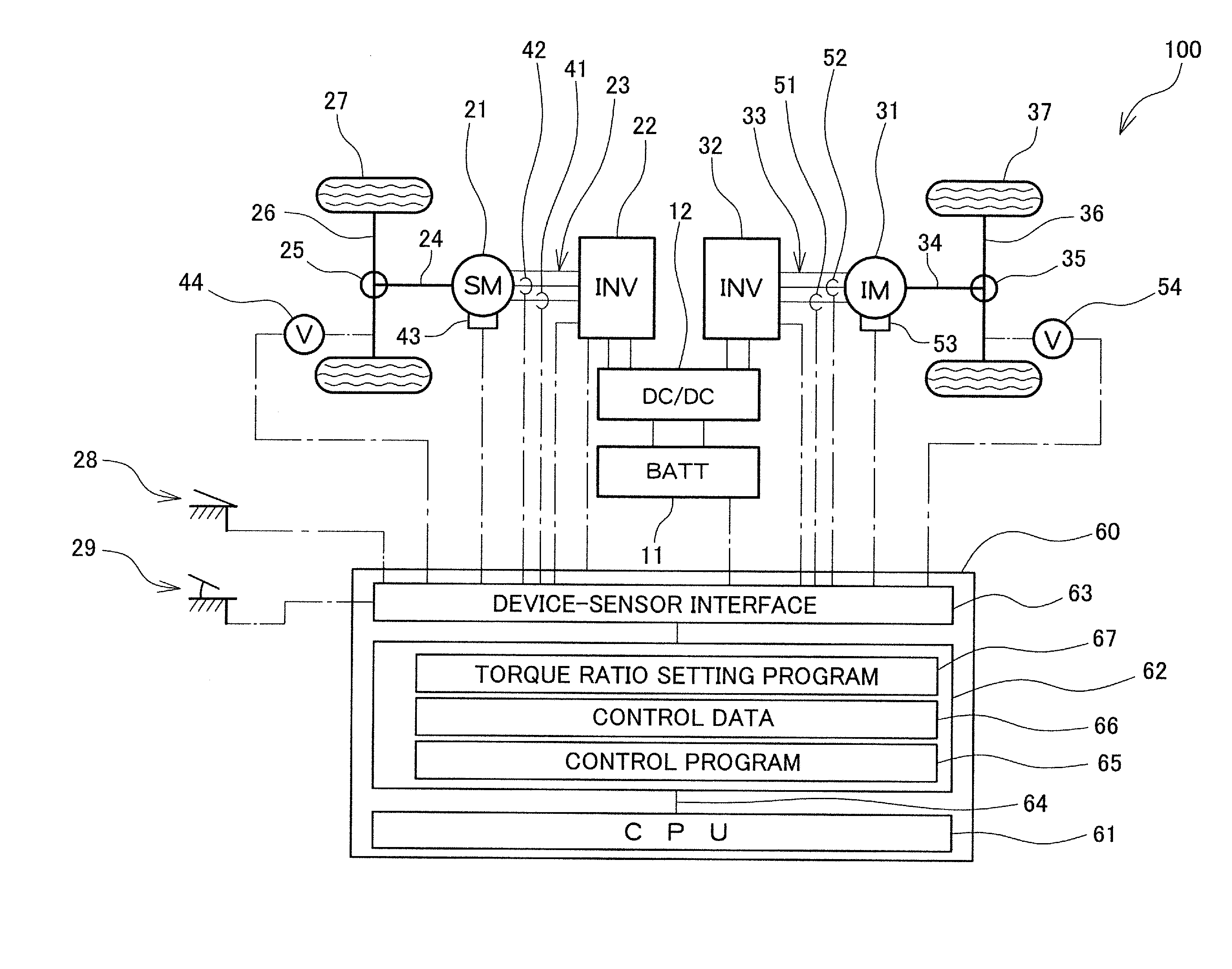
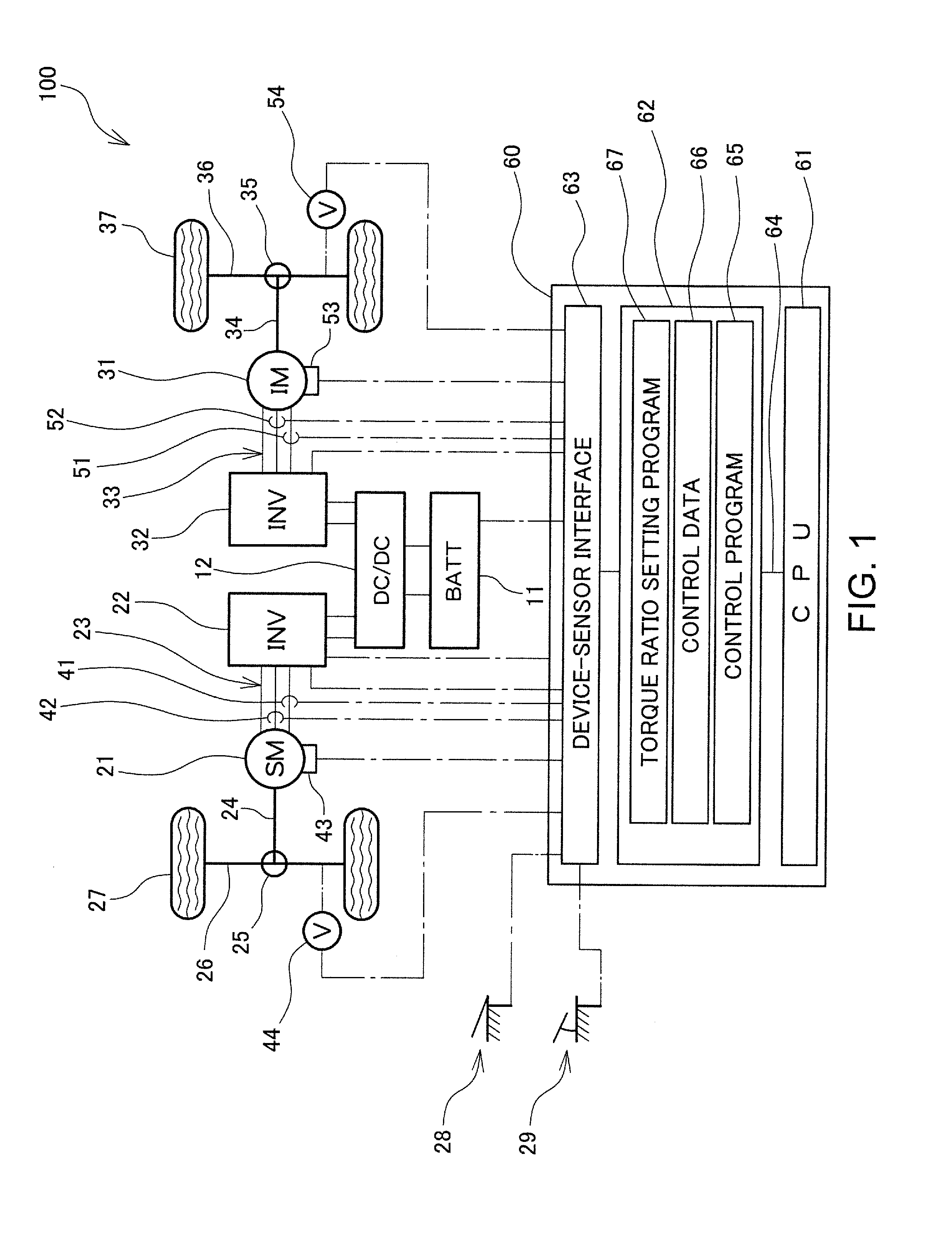
[0023]Embodiments of the present invention are described below with reference to the attached drawings. As shown in FIG. 1, an electric vehicle 100 according to an embodiment of the present invention is provided with front wheels 27 driven with a first drive torque T1 generated by a synchronous motor generator 21 which is a synchronous motor, and rear wheels 37 driven with a second drive torque T2 generated by an induction motor generator 31 which is an induction motor. The electric vehicle 100 brakes the front wheels 27 and the rear wheels 37 respectively with a first regenerative torque BT1 generated by the synchronous motor generator 21 and a second regenerative torque BT2 generated by the induction motor generator 31. Accordingly, the sum of the first drive torque T1 generated by the synchronous motor generator 21 and the second drive torque T2 generated by the induction motor generator 31 (T1+T2) is a total drive torque T of the electric vehicle 100; and the sum of the first re...


PUM


Abstract

An electric vehicle driven by a synchronous motor 21 and an induction motor 31, and braked with a first regenerative torque BT1 generated by the synchronous motor generator 21 and a second regenerative torque BT2 generated by the induction motor generator 31. The ratio of the first regenerative torque BT1 to the second regenerative torque BT2 is changed in accordance with a state of charge (SOC) of a battery 11. In this way, a switching frequency from a regenerative brake to a hydraulic brake is restricted to improve drivability when a state of charge (SOC) of the battery 11 is high.

Description

CROSS-REFERENCE TO RELATED APPLICATION[0001]This application claims priority to Japanese Patent Application No. 2014-003399, filed on Jan. 10, 2014, which is incorporated herein by reference in its entirety.BACKGROUND[0002]1. Technical Field[0003]The present invention relates to an electric vehicle, and more particularly to a structure of an electric vehicle driven by a synchronous motor and an induction motor, and a control method of the electric vehicle.[0004]2. Related Art[0005]Recently, electric vehicles driven by an electric motor are in widespread use. There are many types of electric motors such as permanent-magnet type synchronous motors, induction motors, and reluctance type motors, with various characteristics. Therefore, it is proposed to configure a drive system of an electric vehicle with desired functions by combining characteristics of two or more types of electric motors to achieve mutually complementary characteristics (refer to, for example, JP H07-15804).[0006]JP ...

Claims


Application Information

Patent Timeline
IPC IPC(8): H02P3/14
CPCH02P3/14B60L7/14B60L7/18B60L7/24B60L2220/12B60L2220/14B60L2240/12B60L58/12H02P3/18H02P5/74Y02T10/64Y02T10/70B60L7/00
Inventor OTA, TAKASHISATO, RYOJISUHAMA, MASAYOSHI
Owner TOYOTA JIDOSHA KK
Why Eureka
Try Eureka