Radio module and relevant manufacturing method

a radio module and manufacturing method technology, applied in the direction of printed circuit aspects, electrical apparatus construction details, stacked spaced pcbs, etc., can solve the problems of difficult to reduce the size and dimension insufficient grounding and cooling performance of the radio board, and existing solutions of the radio board. achieve the effect of reducing the size and dimension

Inactive Publication Date: 2015-07-16
TELEFON AB LM ERICSSON (PUBL)
View PDF4 Cites 6 Cited by
  • Summary
  • Abstract
  • Description
  • Claims
  • Application Information

AI Technical Summary

Benefits of technology

[0011]According to one or more embodiments of the present invention, at least one novel stack-up radio module can be mounted on a maim board, which will decrease size and dimension compared with current single-side / double-side mounted radio boards. In addition, such radio modules according to one or more embodiments of the present invention enable modulization design in the demand of different functionality.

Problems solved by technology

However, existing solutions of radio boards have some disadvantages.
For example, for single-side mounted boards, all components are mounted on the front surface of the board, which makes difficult to decrease the size and dimension of the board.
For double-side mounted boards, although proving relatively small size and dimension, grounding and cooling performance are not good enough for radio circuits.
For both single-mounted and double-mounted boards, separated EMC cover(s), which is necessary for shielding, increases the weight and cost of a unit consisting of one or more boards.
Moreover, in the existing solutions all the components are mounted on one board (either a single-mounted board or a double-mounted board), which leads to less flexibility when meeting failure problem or function / performance upgrade.

Method used


Image

  • Radio module and relevant manufacturing method
  • Radio module and relevant manufacturing method
  • Radio module and relevant manufacturing method

Examples


Embodiment Construction

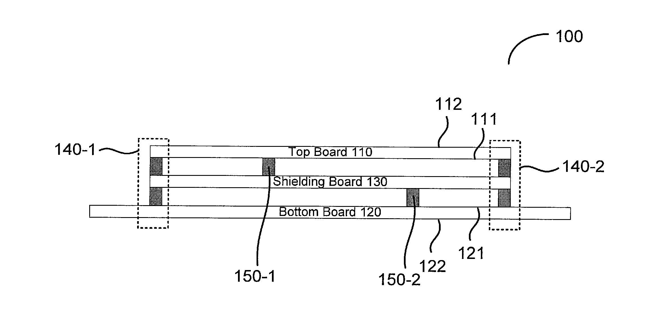
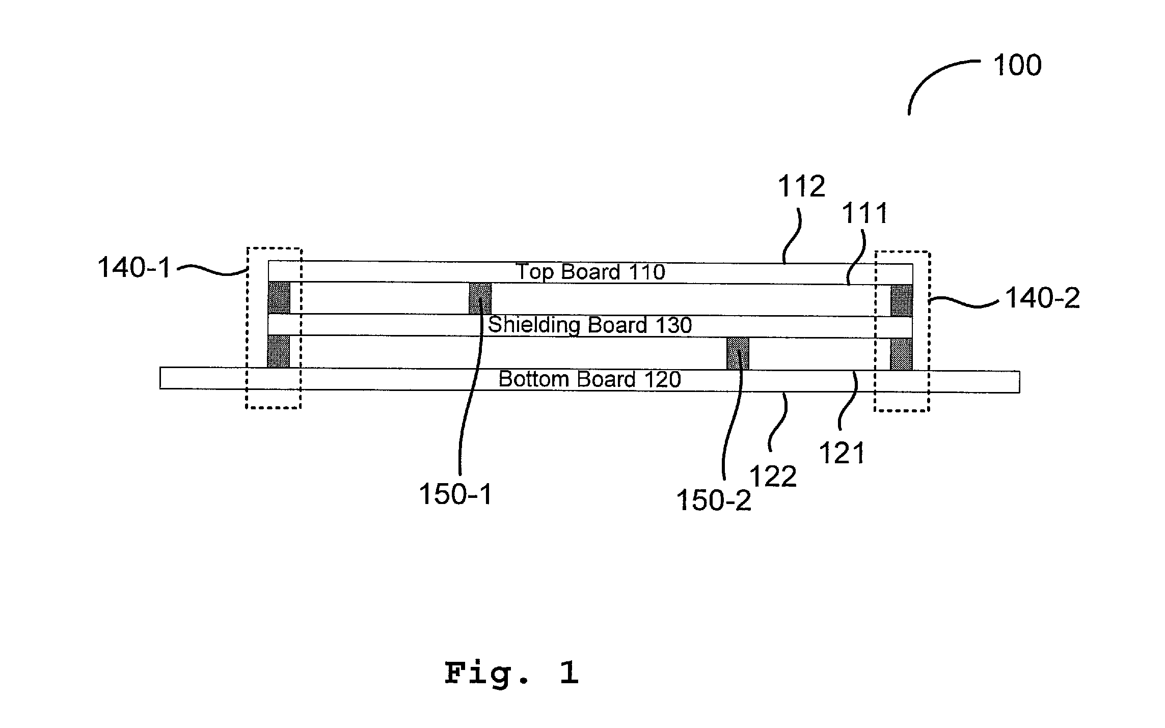
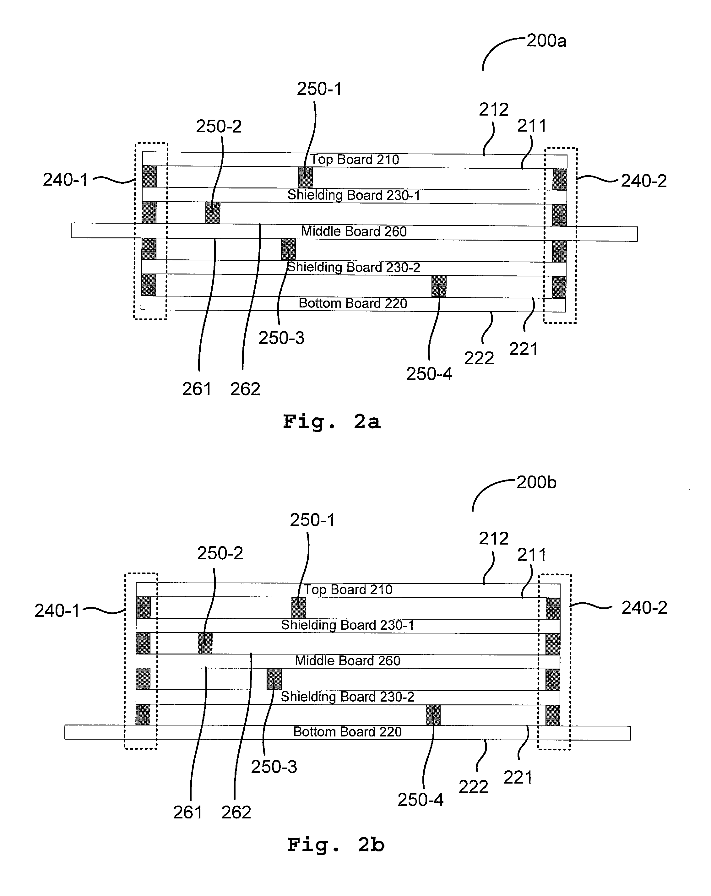
[0018]Hereinafter, embodiments of the present invention will be described with reference to the accompanying drawings. In the following description, many specific details are illustrated so as to understand the present invention more comprehensively. However, it is apparent to the skilled in the art that implementation of the present invention may not have these details. Additionally, it should be understood that the present invention is not limited to the particular embodiments as introduced here. On the contrary, any arbitrary combination of the following features and elements may be considered to implement and practice the present invention, regardless of whether they involve different embodiments. Thus, the following aspects, features, embodiments and advantages are only for illustrative purposes, and should not be understood as elements or limitations of the appended claims, unless otherwise explicitly specified in the claims. Throughout the drawings, the same reference numeral...


PUM


Abstract

A radio module comprises a top board (110) with all components mounted on a front surface (111) and a metal substrate on a back surface (112); a bottom board (120) with all components mounted on a front surface (121) and a metal substrate on a back surface (122), wherein the bottom board (120) is arranged so that the front surface (121) of the bottom board (120) is opposite to the front surface (111) of the top board (110); and at least one shielding board (130) provided between the top board (110) and the boom board (120) with certain vertical spacing. The top board (110), the bottom board (120), and the at least one shielding board (130) are arranged to be substantially in alignment in a vertical direction and be fastened with one another. A board-board electrical connection (140-1, 140-2) is established at least between the top board (110) and the bottom board (120).

Description

TECHNICAL FIELD[0001]The embodiments of the present invention generally relate to printed circuit boards (PCBs), particularly to radio modules operatively connected with a main board.DESCRIPTION OF THE RELATED ART[0002]Single-side mounted radio boards and double-side mounted radio boards are widely adopted in almost all today's radio unit.[0003]Typically, a single-side mounted PCB, which has all its components mounted on its front surface and has a metal substrate formed on its back surface, can provide more effective grounding and cooling performance. A double-side mounted PCB, which has its components mounted on both its front and back surfaces, typically offers a relatively small PCB size and board dimension. Here, the components of PCBs as mentioned above may include active and passive elements such as resistors, capacitor, inductors, transformers, filters, mechanical switches, relays and so on.[0004]For a radio PCB, in order to get very good reference for micro-strip for radio ...

Claims


Application Information

Patent Timeline
Patent Type & Authority Applications(United States)
IPC IPC(8): H05K1/14H05K9/00H05K1/02
CPCH05K1/144H05K2201/10734H05K9/00H05K1/0203H05K9/0024H05K1/0209H05K3/0061H05K2201/042H05K2201/066H05K2201/0715H05K2201/10371H05K2201/10098
Inventor LIAO, JICHANGSUN, NING
Owner TELEFON AB LM ERICSSON (PUBL)
Why Eureka
Try Eureka