System and Method for Installing a Manifold Plug

a manifold and plug technology, applied in the field of plugs, can solve the problems of inability to adjust the installation gun does not appear to include releasably secured and interchangeable end pieces, and the tool does not appear to have any depth control for controlling the installation depth of the insert. , to achieve the effect of convenient insert handling

Active Publication Date: 2015-07-23
ENGINEERED INSERTS & SYST
View PDF14 Cites 30 Cited by
  • Summary
  • Abstract
  • Description
  • Claims
  • Application Information

AI Technical Summary

Benefits of technology

[0007]Therefore, it is an object of the present invention to provide an insert that can be installed without a stem.
[0008]It is yet another object of the present invention to provide an installation device that aids in the installation of the insert.
[0011]It is still another object of the present invention to provide an insert that can withstand high pressures typically found in hydraulic manifolds.
[0012]These and other objects are achieved by providing an insert with a tapered core and a cylinder. The core releasably secures to an installation device. The installation device includes a depth stop or a depth control to control the installation depth of the insert. The insert may be installed in a tray that allows for easier handling of the inserts and installation thereof. In some cases, the core includes a threaded hole to releasably secure the insert to the installation device.

Problems solved by technology

The manufacturing of the stem can be a complicated and expensive process as the stem must break off at the appropriate force in order to properly install the plug.
Further, the tool does not appear to have any depth control for controlling the installation depth of the insert.
Further, the installation gun does not appear to include releasably secured and interchangeable end pieces.

Method used


Image

  • System and Method for Installing a Manifold Plug
  • System and Method for Installing a Manifold Plug
  • System and Method for Installing a Manifold Plug

Examples


Embodiment Construction

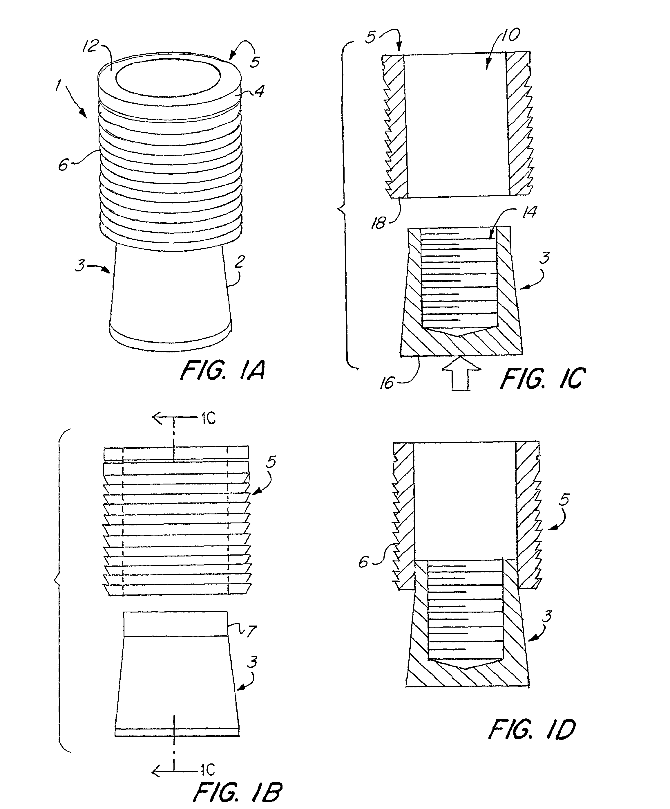
[0032]In FIG. 1A-D, the insert 1 has two sections. As shown, core 3 has a tapered wall 2 and an upper cylindrical section 7. In some embodiments, the tapered section will extend from the top of the core towards the bottom. In some cases, a rounded section is disposed at the top of the core and the taper extends at the end of the rounded section. Cylindrical sleeve 5 has an outer surface which may include ridges or rings 6. The ridges may interact with an installation hole in order to better secure or seal the plug to the hole. Although ridges are shown, it is understood that other textures can be used on the outside of the plug. In the illustrated embodiment, the series of rings provide both additional resistance and friction against the inside of the installation hole. The rings can further act as flow stops that can help to prevent leakage through the installation hole when the insert is installed in the installation hole as fluid would need to pass beyond each of the ridges. Ther...


PUM

PropertyMeasurementUnit
pressuresaaaaaaaaaa
taper angleaaaaaaaaaa
dimensionaaaaaaaaaa

Abstract

The present disclosure relates to an insert and system of installing the same. The insert includes a tapered core and a cylinder. The core releasably secures to an installation device which includes a depth stop or a depth control to control the installation depth of the insert. The insert may be provided in a tray that allows for easier handling of the inserts and installation thereof in installation holes, for example in a hydraulic manifold. In some cases, the core includes a threaded hole to releasably secure the insert to the installation device, thus allowing the installation device to pull the core into the cylinder. The core and cylinder may be made of metallic materials such as steels, steel alloys and others. In some cases the insert can withstand blow out pressures of 40,000 psi or higher.

Description

FIELD OF THE INVENTION[0001]The following disclosure relates to a plug and a system, kit and method for installing the same. More particularly, the plug may be designed to seal manifolds or other devices that may have holes therein, for example, a hydraulic manifold.BACKGROUND OF THE INVENTION[0002]There are various plug and sealing systems generally known. For example, some commercially available plugs include a rivet system having a stem that is designed to break off during installation of the plug in a hole. The stem acts similar to a pop rivet. The manufacturing of the stem can be a complicated and expensive process as the stem must break off at the appropriate force in order to properly install the plug.[0003]US Pat. No. 4,584,755 to Lundquist discloses a tool and a plug for sealing a hole, for example, an unused coolant passage in an injection molding die. The plug includes a flexible, hollow cylindrical sleeve and a core member longitudinally interengageable into the sleeve. ...

Claims


Application Information

Patent Timeline
Patent Type & Authority Applications(United States)
IPC IPC(8): B25B27/00F16B21/10
CPCB25B27/0014F16B21/10B25B27/0028B25B23/0064B25B27/04F16B13/0858F16L55/1108F16L55/13Y10T29/4994Y10T29/53691
Inventor KIRILICHIN, VICTORTURECHEK, DAVID P.KRIEGER, BRIAN P.
Owner ENGINEERED INSERTS & SYST
Why Eureka
Try Eureka