Charging apparatus with dynamical charging power and method of operating the same

a charging apparatus and dynamic technology, applied in the direction of electrochemical generators, secondary cells servicing/maintenance, transportation and packaging, etc., can solve the problem that the output power generated by only the ac electric grid for the charging station cannot provide high charging demands and charging qualities

Active Publication Date: 2015-07-23
DELTA ELECTRONICS INC
View PDF32 Cites 31 Cited by
  • Summary
  • Abstract
  • Description
  • Claims
  • Application Information

AI Technical Summary

Benefits of technology

[0006]An object of the present disclosure is to provide a charging apparatus with dynamical charging power configured to charge an electric vehicle to solve the above-mentioned problems. Accordingly, the charging apparatus includes a main power conversion unit, an auxiliary power conversion unit, and a control unit. The main power conversion unit receives an AC power and converts the AC power into a main output power. The auxiliary power conversion unit receives an auxiliary DC power and converts the auxiliary DC power into an auxiliary output power. The control unit controls maximum output power of the main output power to be an upper-limit output power value. The control unit dynamically controls the auxiliary output power according to a power difference value between a charging power value and the upper-limit output power value when the charging power value of charging the electric vehicle is greater than the upper-limit output power value.

Problems solved by technology

In addition, the output power generated from only the AC electric grids for the charging stations cannot provide high charging demands and charging qualities because of the limited output power generated from electric grids in remote areas or the evaluation of demand charges by the industries of charging stations.

Method used


Image

  • Charging apparatus with dynamical charging power and method of operating the same
  • Charging apparatus with dynamical charging power and method of operating the same
  • Charging apparatus with dynamical charging power and method of operating the same

Examples


first embodiment

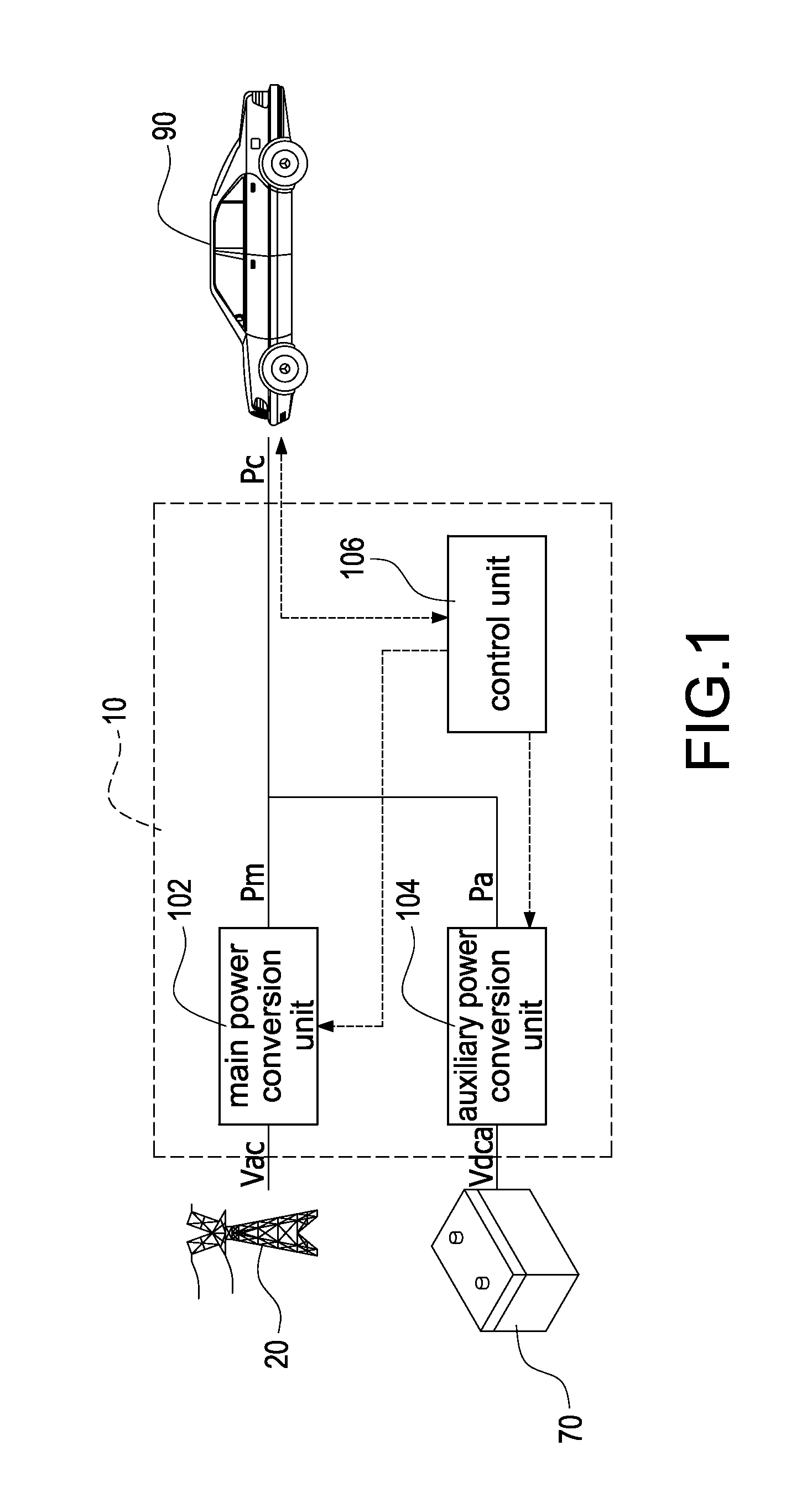
[0018]Reference is made to FIG. 1 which is a schematic circuit block diagram of a charging apparatus with dynamical charging power according to the present disclosure. The charging apparatus 10 with dynamical charging power is provided to charge an electric vehicle 90. The charging apparatus 10 with dynamical charging power includes a main power conversion unit 102, an auxiliary power conversion unit 104, and a control unit 106. The main power conversion unit 102 receives an AC power Vac outputted from an AC electric grid 20, and converts the AC power Vac into a main output power Pm. The auxiliary power conversion unit 104 receives an auxiliary DC power Vdca and converts the auxiliary DC power Vdca into an auxiliary output power Pa. Especially, the auxiliary DC power Vdca can be outputted from a secondary battery 70 (also referred to as a rechargeable battery. The control unit 106 controls maximum output power of the main output power Pm to be an upper-limit output power value Pu. T...

second embodiment

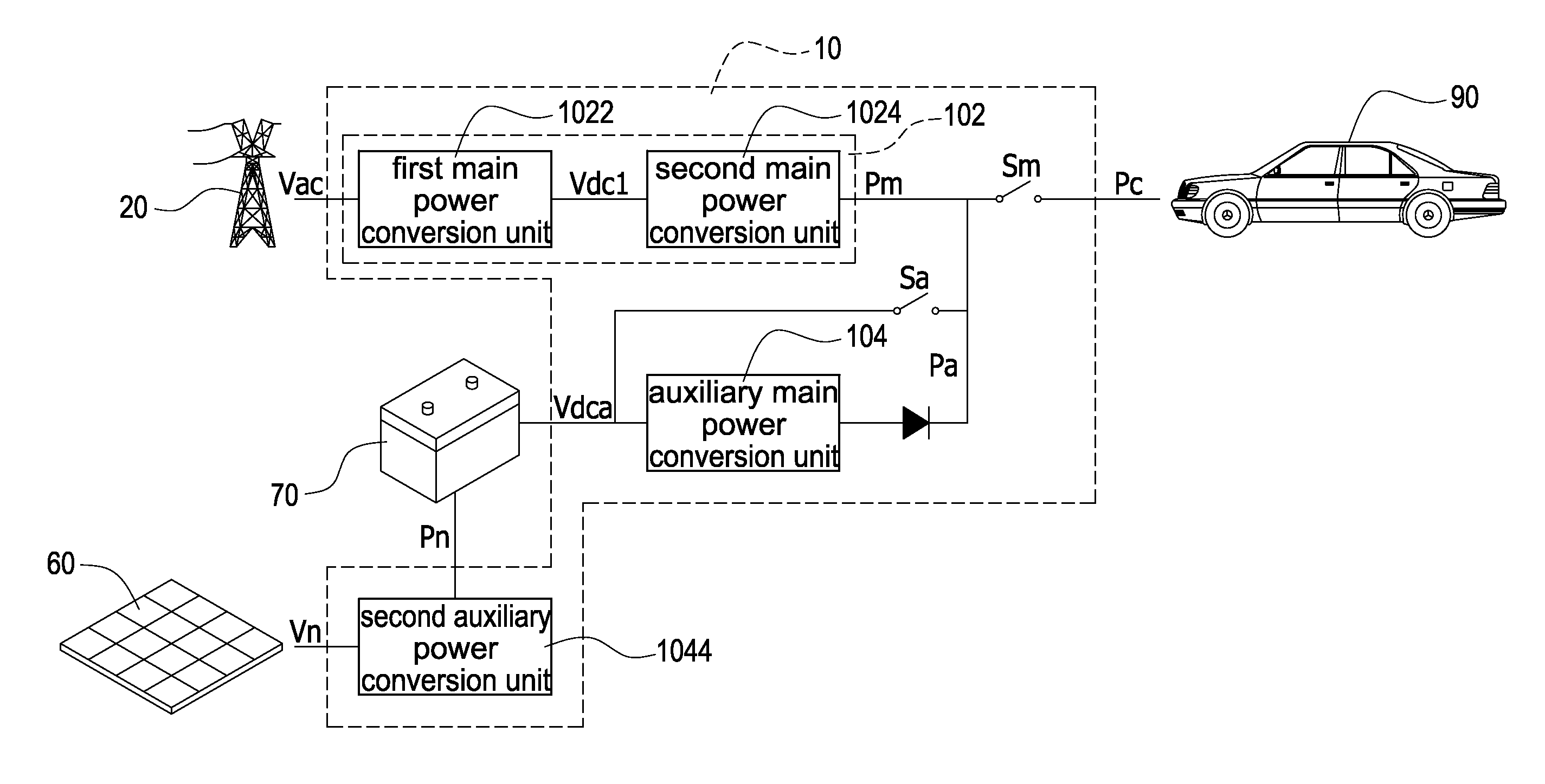
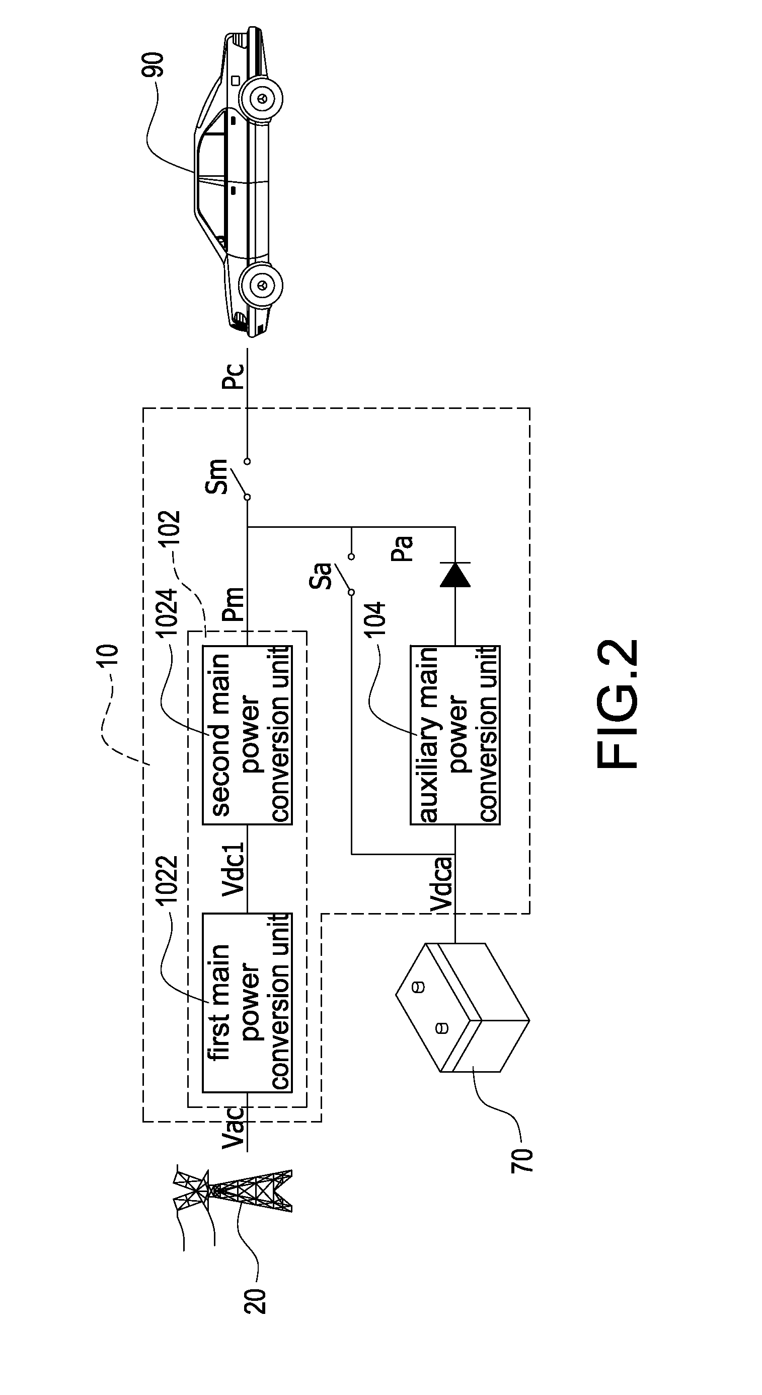
[0019]Reference is made to FIG. 2 which is a schematic circuit block diagram of the charging apparatus with dynamical charging power according to the present disclosure. The main power conversion unit 102 includes a first main power conversion unit 1022 and a second main power conversion unit 1024. The first main power conversion unit 1022 receives the AC power Vac and converts the AC power Vac into a first DC power Vdc1. The second main power conversion unit 1024 receives the first DC power Vdc1 and converts the first DC power Vdc1 into the main output power Pm. In particular, the first main power conversion unit 1022 is an AC-to-DC converter to convert the AC power Vac into the first DC power Vdc1. The second main power conversion unit 1024 is a DC-to-DC converter to convert a voltage level of the first DC power Vdc1 into the required voltage level for charging the electric vehicle 90. The auxiliary power conversion unit 104 is a DC-to-DC converter to convert a voltage level of th...


PUM


Abstract

A charging apparatus with dynamical charging power is configured to charge an electric vehicle. The charging apparatus includes a main power conversion unit, an auxiliary power conversion unit, and a control unit. The main power conversion unit receives an AC power and converts the AC power into a main output power. The auxiliary power conversion unit receives an auxiliary DC power and converts the auxiliary DC power into an auxiliary output power. The control unit controls maximum output power of the main output power to be an upper-limit output power value. When a charging power value of charging the electric vehicle is greater than the upper-limit output power value, the control unit dynamically controls the auxiliary output power according to a power difference value between the charging power value and the upper-limit output power value.

Description

BACKGROUND[0001]1. Technical Field[0002]The present disclosure relates generally to a charging apparatus with dynamical charging power and a method of operating the same, and more particularly to a charging apparatus with dynamical charging power applied to an electric vehicle and a method of operating the same.[0003]2. Description of Related Art[0004]In recent years, the technology developments of electric vehicles and charging stations have received much attention because of high oil prices and extensions of environmental protection by governmental and non-governmental organizations. In order to reduce that the charging apparatus is excessively dependent on the AC electric grid, however, the current regulations specify the maximum output power of the AC electric grid for the charging apparatus. In addition, the output power generated from only the AC electric grids for the charging stations cannot provide high charging demands and charging qualities because of the limited output p...

Claims


Application Information

Patent Timeline
Patent Type & Authority Applications(United States)
IPC IPC(8): B60L11/18H02J7/35H02J7/00
CPCB60L11/1811H02J7/35H02J7/007H02J7/34Y02T10/7072Y02T90/14Y04S10/126B60L53/20B60L53/31B60L53/63Y02E60/00Y02T10/70Y02T90/12H02J3/322H02J2310/48Y04S30/12Y02T90/167H02J5/00Y02T90/16
Inventor CHANG, YU-MING
Owner DELTA ELECTRONICS INC
Why Eureka
Try Eureka