Controller for internal combustion engine with supercharger

A technology of supercharger and internal combustion engine, applied in engine control, fuel injection control, internal combustion piston engine, etc., can solve the problem of increased power generation of alternator, inability to obtain driver supercharging performance, and undisclosed auxiliary compressor control method And other issues

Active Publication Date: 2006-09-06
DENSO CORP
View PDF4 Cites 30 Cited by
  • Summary
  • Abstract
  • Description
  • Claims
  • Application Information

AI Technical Summary

Problems solved by technology

[0006] However, the above publication does not disclose how to control the control method of the auxiliary compressor
Therefore, it is difficult to operate the auxiliary compressor with a proper amount of control
For example, in a configuration in which the auxiliary compressor is operated by an electric motor, etc., when the auxiliary compressor operates un...

Method used


Image

  • Controller for internal combustion engine with supercharger
  • Controller for internal combustion engine with supercharger
  • Controller for internal combustion engine with supercharger

Examples


no. 1 example

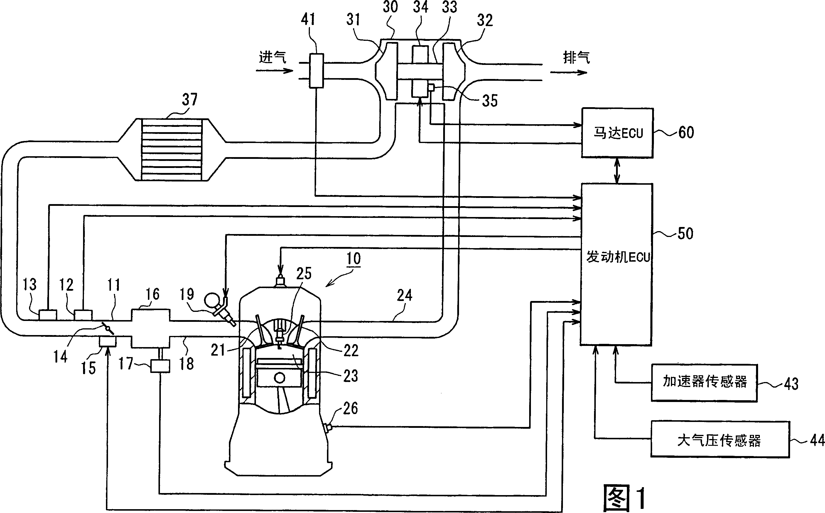
[0047] Embodiments of the present invention will be described below with reference to the accompanying drawings. In the embodiment, the engine control system is configured to be used on a vehicle with a multi-cylinder gasoline engine as an internal combustion engine, and the engine of the control system is equipped with an electric auxiliary turbocharger (hereinafter also referred to as an electric turbocharger) as a supercharger device. First, an overall schematic configuration diagram of an engine control system will be described with reference to FIG. 1 .

[0048] In an engine 10 as shown in FIG. 1 , an intake pipe 11 is provided with a throttle valve 14 as an air volume adjusting device, the position of which is adjusted by a throttle valve actuator 15 such as a DC motor or the like. The throttle actuator 15 includes a throttle position sensor for detecting the position of the throttle. On the upstream side of the throttle valve 14, a boost pressure sensor 12 for detecti...

no. 2 example

[0145] Fig. 18 is an overall schematic configuration diagram of an engine control system. The same reference numerals are assigned to the same components as in the first embodiment and description will not be repeated. The description of the same operation will not be repeated.

[0146] In the intake pipe 11 , an auxiliary electric compressor 38 is arranged on the compressor upstream side of the turbocharger 30 . Intake air is compressed on the upstream side of the turbocharger 30 by an auxiliary compressor 38 . The auxiliary compressor 38 uses a motor 38a as a drive source. The auxiliary compressor 38 operates when the motor 38a is powered by power from a battery (not shown). That is, unlike the turbocharger 30 , the auxiliary compressor 38 uses a different power than the exhaust gas as its power source.

[0147] The engine ECU 50 determines the control amount of the auxiliary compressor 38 (motor 38a) interlocked with the torque basic control. Therefore, when the vehicl...

no. 3 example

[0193] Figure 30 It is an overall schematic configuration diagram of the engine control system.

[0194] exist Figure 30 In the illustrated engine 210 , a piston 212 is housed in a cylinder block 211 , and a combustion chamber 214 is bounded by the inner walls of the cylinder, the piston 212 and the cylinder head 213 . An electronically controlled fuel injection valve 215 is arranged in the cylinder head 213 . High-pressure fuel is supplied from the common rail 216 to the fuel injection valve 215 , and the fuel is injected into the combustion chamber 214 by the opening operation of the fuel injection valve 215 . Although not shown, the system has a fuel pump for pressure delivery of fuel in the fuel tank into common rail 216 . The fuel pump fuel discharge amount is controlled based on the pressure (fuel pressure) in the common rail detected by a sensor or the like.

[0195] An intake valve 217 is arranged for the intake port, and an exhaust valve 218 is arranged for the ...


PUM


Abstract

A torque base control unit calculates target torque based on an accelerator position and engine speed. The control unit further executes calculation of target airflow rate, calculation of target intake pressure, and calculation of target boost pressure based on the target torque. Target throttle position is calculated based on the target airflow rate, target intake pressure, target boost pressure, actual boost pressure, and throttle passed intake temperature. An assist control unit calculates target turbine power based on the target airflow rate and the target boost pressure calculated by the torque base control unit and calculates actual turbine power based on exhaust information. Assist power of a motor attached to a turbocharger is calculated based on the power difference between the target turbine power and the actual turbine power.

Description

technical field [0001] The present invention relates to a controller applied to an internal combustion engine having a supercharger such as a turbocharger, which controller appropriately controls auxiliary power to the supercharger. Background technique [0002] A turbocharger is well known as a supercharger that supercharges intake air by using exhaust power. In recent years, an electrically assisted turbocharger has been developed in which an electric motor or the like is attached to a rotary shaft of the turbocharger and assists exhaust power in accordance with the operating state of the internal combustion engine. [0003] The controller disclosed in JP-11-117933A controls the current through the electric motor based on the accelerator stroke amount and the accelerator stroke speed, thus facilitating the supercharging operation of the turbocharger. The controller disclosed in JP-11-280510A controls the throttle opening speed and the current through the motor according t...

Claims


Application Information

Patent Timeline
IPC IPC(8): F02D41/04
CPCY02T10/144Y02T10/12
Inventor 木本佳代子矶部大治
Owner DENSO CORP
Why Eureka
Try Eureka