Controller for internal combustion engine with supercharger
A technology of supercharger and internal combustion engine, applied in engine control, fuel injection control, internal combustion piston engine, etc., can solve the problems of undisclosed auxiliary compressor control method, difficult to control quantity, unable to obtain driver's supercharging performance, etc.
- Summary
- Abstract
- Description
- Claims
- Application Information
AI Technical Summary
Problems solved by technology
Method used
Image
Examples
no. 1 example
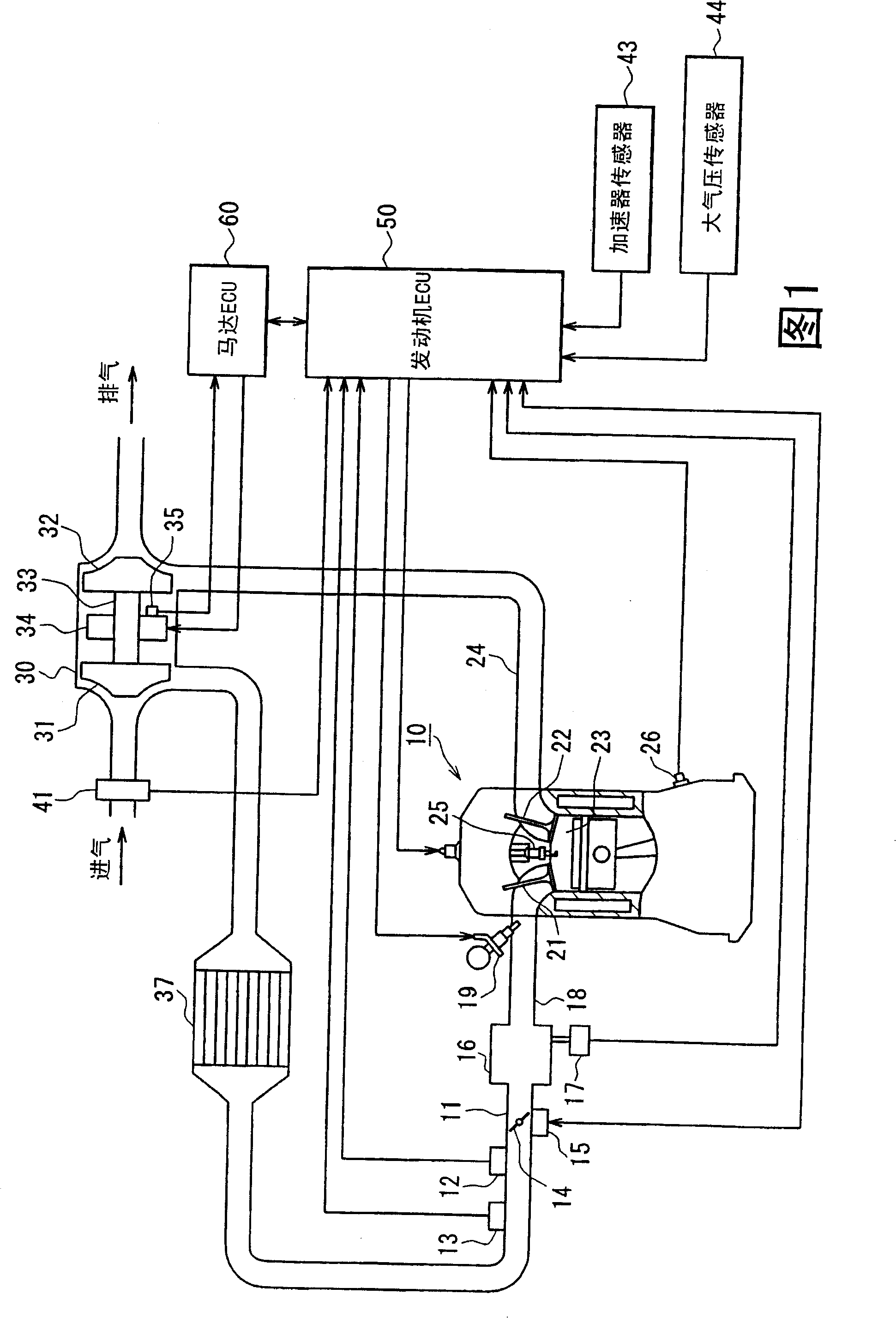
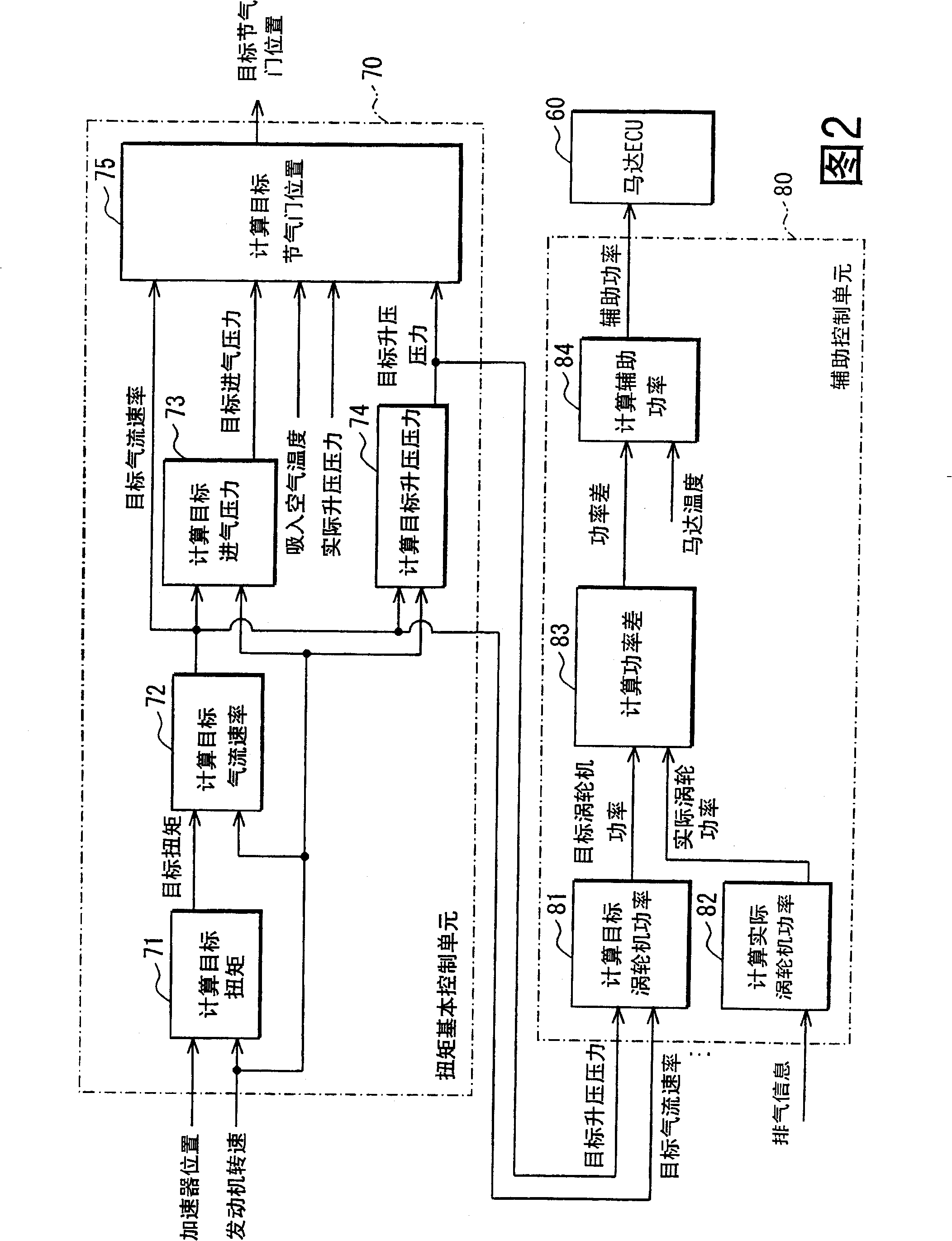
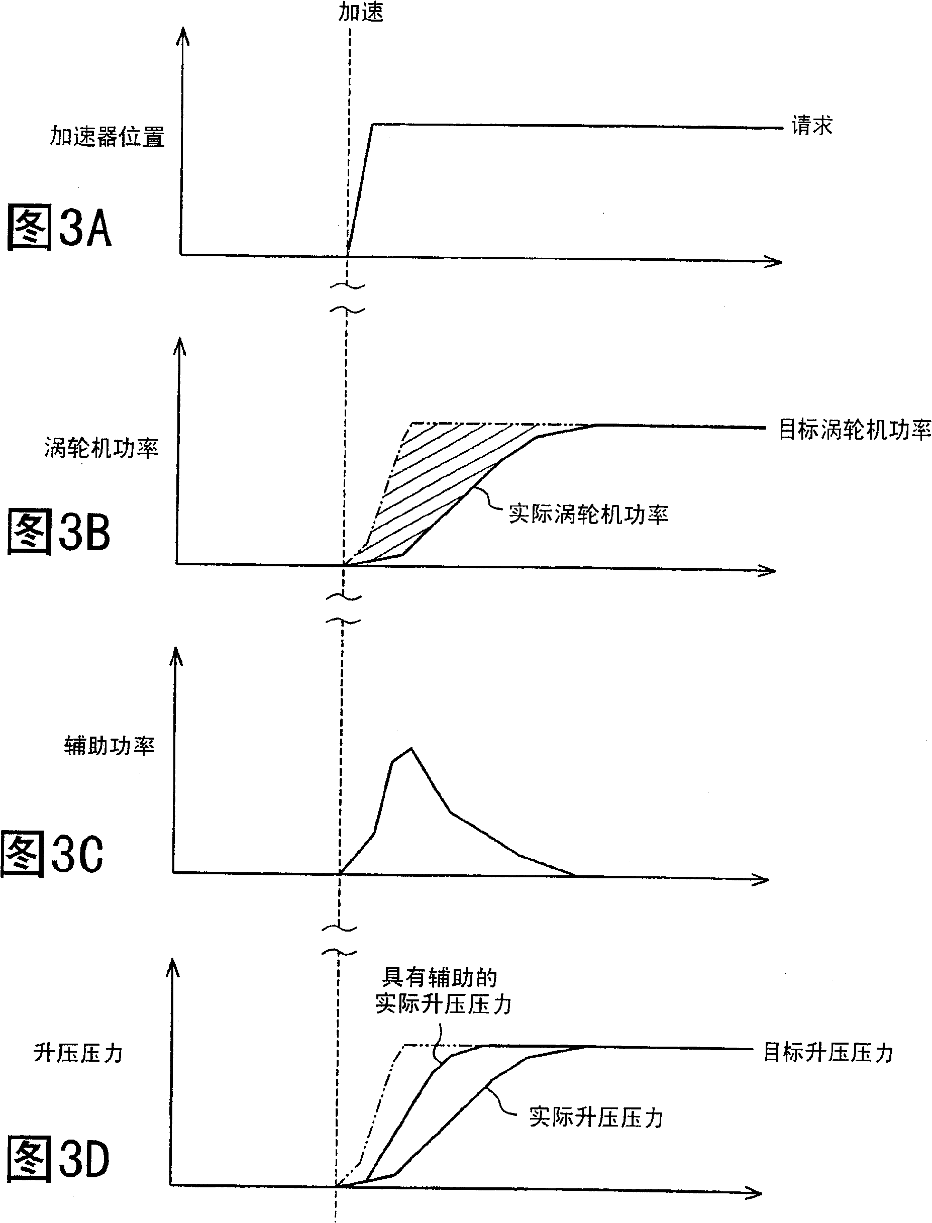
[0047] Embodiments of the present invention will be described below with reference to the accompanying drawings. In the embodiment, the engine control system is configured to be used on a vehicle with a multi-cylinder gasoline engine as an internal combustion engine, and the engine of the control system is equipped with an electric auxiliary turbocharger (hereinafter also referred to as an electric turbocharger) as a supercharger device. First, an overall schematic configuration diagram of an engine control system will be described with reference to FIG. 1 .
[0048] In an engine 10 as shown in FIG. 1 , an intake pipe 11 is provided with a throttle valve 14 as an air volume adjusting device, the position of which is adjusted by a throttle valve actuator 15 such as a DC motor or the like. The throttle actuator 15 includes a throttle position sensor for detecting the position of the throttle. On the upstream side of the throttle valve 14, a boost pressure sensor 12 for detecti...
no. 2 example
[0145] Fig. 18 is an overall schematic configuration diagram of an engine control system. The same reference numerals are assigned to the same components as in the first embodiment and description will not be repeated. The description of the same operation will not be repeated.
[0146] In the intake pipe 11 , an auxiliary electric compressor 38 is arranged on the compressor upstream side of the turbocharger 30 . Intake air is compressed on the upstream side of the turbocharger 30 by an auxiliary compressor 38 . The auxiliary compressor 38 uses a motor 38a as a drive source. The auxiliary compressor 38 operates when the motor 38a is powered by power from a battery (not shown). That is, unlike the turbocharger 30 , the auxiliary compressor 38 uses a different power than the exhaust gas as its power source.
[0147] The engine ECU 50 determines the control amount of the auxiliary compressor 38 (motor 38a) interlocked with the torque basic control. Therefore, when the vehicl...
no. 3 example
[0193] Figure 30 It is an overall schematic configuration diagram of the engine control system.
[0194] exist Figure 30 In the illustrated engine 210 , a piston 212 is housed in a cylinder block 211 , and a combustion chamber 214 is bounded by the inner walls of the cylinder, the piston 212 and the cylinder head 213 . An electronically controlled fuel injection valve 215 is arranged in the cylinder head 213 . High-pressure fuel is supplied from the common rail 216 to the fuel injection valve 215 , and the fuel is injected into the combustion chamber 214 by the opening operation of the fuel injection valve 215 . Although not shown, the system has a fuel pump for pressure delivery of fuel in the fuel tank into common rail 216 . The fuel pump fuel discharge amount is controlled based on the pressure (fuel pressure) in the common rail detected by a sensor or the like.
[0195] An intake valve 217 is arranged for the intake port, and an exhaust valve 218 is arranged for the ...
PUM
 Abstract
Description
Claims
Application Information
 - R&D
- Intellectual Property
- Life Sciences
- Materials
- Tech Scout
- Unparalleled Data Quality
- Higher Quality Content
- 60% Fewer Hallucinations
Browse by: Latest US Patents, China's latest patents, Technical Efficacy Thesaurus, Application Domain, Technology Topic, Popular Technical Reports.
© 2025 PatSnap. All rights reserved.Legal|Privacy policy|Modern Slavery Act Transparency Statement|Sitemap|About US| Contact US: help@patsnap.com


