Voltage conversion apparatus, power output apparatus, and control method of voltage converter

Active Publication Date: 2007-08-30
TOYOTA JIDOSHA KK
View PDF5 Cites 30 Cited by
  • Summary
  • Abstract
  • Description
  • Claims
  • Application Information

AI Technical Summary

Benefits of technology

[0011]According to an aspect of the present invention, a voltage conversion apparatus includes a voltage converter, a control device, and a sensor device. The voltage converter is provided between a DC power source and a driving device that drives at least one electric motor in one of a power running mode and regeneration mode. The control device is configured to boost the voltage from the DC power source by controlling the voltage converter within a range that does not exceed an upper limit value. The sensor device senses the power input to and output from the DC power source. The control device r

Problems solved by technology

However, the publication of Japanese Patent Laying-Open No. 2004-229399 is silent about a problem of the inverter voltage (the voltage between the boost converter and inverter) attaining an overvoltage level when the power balance of the AC motor is continuously at the regeneration side.
However, when the pow

Method used


Image

  • Voltage conversion apparatus, power output apparatus, and control method of voltage converter
  • Voltage conversion apparatus, power output apparatus, and control method of voltage converter
  • Voltage conversion apparatus, power output apparatus, and control method of voltage converter

Examples


Embodiment Construction

[0031]Embodiments of the present invention will be described hereinafter with reference to the drawings. In the drawings, the same or corresponding elements have the same reference characters allotted, and description thereof will not be repeated.

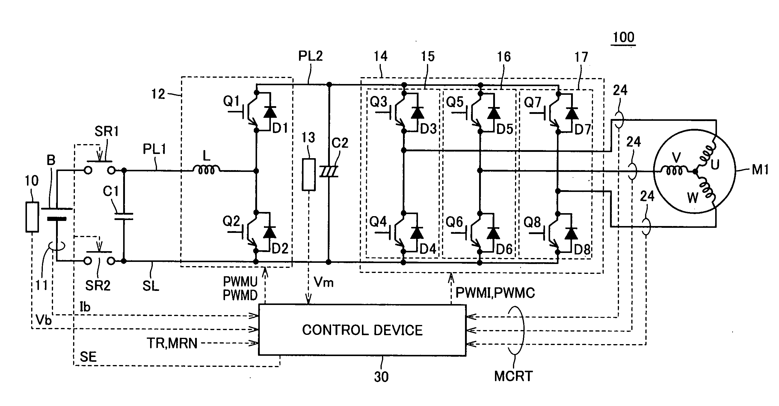
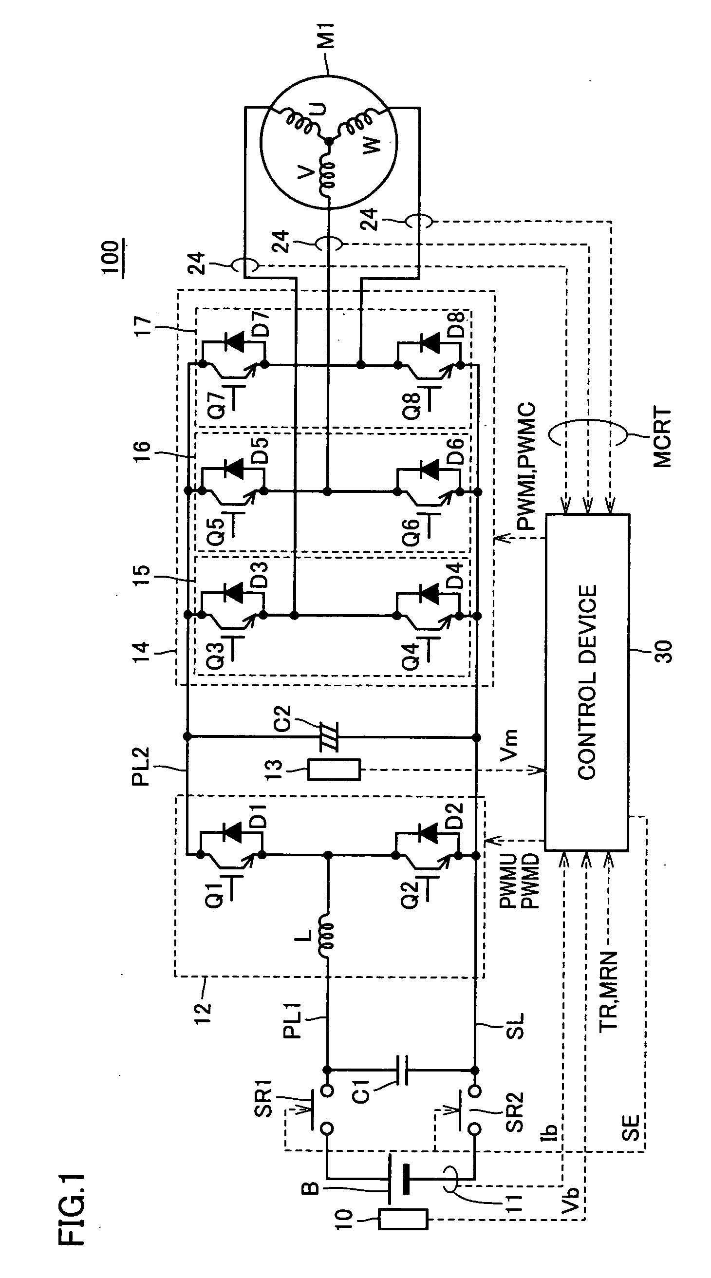
[0032]FIG. 1 is a circuit diagram of a motor driving device including a voltage conversion apparatus according to an embodiment of the present invention. Referring to FIG. 1, a motor driving device 100 includes a DC power source B, voltage sensors 10 and 13, system relays SR1 and SR2, capacitors C1 and C2, a boost converter 12, an inverter 14, current sensors 11 and 24, and a control device 30.

[0033]Motor driving device 100 is incorporated in a motorized vehicle such as a hybrid vehicle, an electric vehicle, and the like. An AC motor M1 is mechanically coupled to a driving wheel, and generates torque to drive the vehicle. Alternatively, AC motor M1 may be mechanically coupled to an engine, and incorporated into a hybrid vehicle as a power g...


PUM


Abstract

An upper limit value setting unit of a control device conducts integration on the change in battery power, and determines whether the integrated value is lower than a preset first threshold value (negative value). When determination is made that the integrated value is lower than the first threshold value, and the battery power difference is lower than the second threshold value (negative value), the upper limit value setting unit sets Vup2 that is lower than the general Vup1 as the upper limit value of the inverter input voltage command.

Description

[0001]This nonprovisional application is based on Japanese Patent Application No. 2006-034195 filed with the Japan Patent Office on Feb. 10, 2006, the entire contents of which are hereby incorporated by reference.BACKGROUND OF THE INVENTION[0002]1. Field of the Invention[0003]The present invention relates to a voltage conversion apparatus, a power output apparatus, and a control method of a voltage converter. Particularly, the present invention relates to control of a voltage converter that converts voltage between a driving device that drives an electric motor in a power running mode or regeneration mode and a DC (Direct Current) power source.[0004]2. Description of the Background Art[0005]Recently, attention is focused on hybrid vehicles and electric vehicles as vehicles taking into account environmental issues.[0006]A hybrid vehicle includes, in addition to a conventional engine, a DC power source, an inverter, and a motor driven by the inverter as the power source. In addition t...

Claims


Application Information

Patent Timeline
IPC IPC(8): H02P3/14
CPCB60L3/003Y02T10/648B60L7/16B60L11/123B60L11/14B60L15/2045B60L2210/20H02M1/32H02M7/797H02P27/08H02P2201/09Y02T10/6217Y02T10/644Y02T10/646Y02T10/7077Y02T10/725Y02T10/7283B60L3/12B60L50/16B60L50/61Y02T10/62Y02T10/64Y02T10/70Y02T10/7072Y02T10/72H02M7/48H02P7/12
Inventor OCHIAI, KIYOEOYANAGI, HIROYUKI
Owner TOYOTA JIDOSHA KK
Why Eureka
Try Eureka