Position and pathway lighting system for a vehicle or combination of vehicles sides undersides rear or trailing wheels and rear or trailing body portion

a technology of illumination system and vehicle, applied in the direction of light source, semiconductor device, transportation and packaging, etc., can solve the problems of less desirable, and achieve the effect of improving safety

Inactive Publication Date: 2015-07-23
SCHOTANUS TODD A
View PDF11 Cites 31 Cited by
  • Summary
  • Abstract
  • Description
  • Claims
  • Application Information

AI Technical Summary

Benefits of technology

[0017]This invention is intended to provide improved safety as pertaining to vehicular operation by supplying an intense field of light from one or more light sources particularly adapted for use at one or more locations along the vehicle's sides, rear axle area, and the rearmost body corners. Said light sources thus create early-warning and increased safety zone by adequate illumination so that the driver may visually ascertain and identify, by means of the side rear-view mirrors, the road surface and area proximate to such, in order to avoid objects or persons proximate. At the same time, said illumination also indicates to persons proximate the precise position and pathway of the body sides, wheels and or rear portion of the vehicle in order to avoid accidental contact.

Problems solved by technology

Other methods including wireless transceivers can also be utilized to control the light sources and lighting system as a whole but could be less desirable due to cost, complexity, and interference problems.

Method used


Image

  • Position and pathway lighting system for a vehicle or combination of vehicles sides undersides rear or trailing wheels and rear or trailing body portion
  • Position and pathway lighting system for a vehicle or combination of vehicles sides undersides rear or trailing wheels and rear or trailing body portion
  • Position and pathway lighting system for a vehicle or combination of vehicles sides undersides rear or trailing wheels and rear or trailing body portion

Examples


Embodiment Construction

[0055]Now with regard to the description of the invention and its preferred embodiments, it is wholly the desire of the inventor to describe completely and without ambiguity, the individual components of said in the clearest and best possible terms. The invention described within this application for patent is relatively simple in design but truly indispensible to the function for which it was conceived, making it all the more enjoyable to both describe and use. In keeping with the directives set forth by the USPTO this information should enable any person with average skill in the field of this art to easily understand, make and use without lengthy experimentation.

Symbols Within the Drawings Clarified

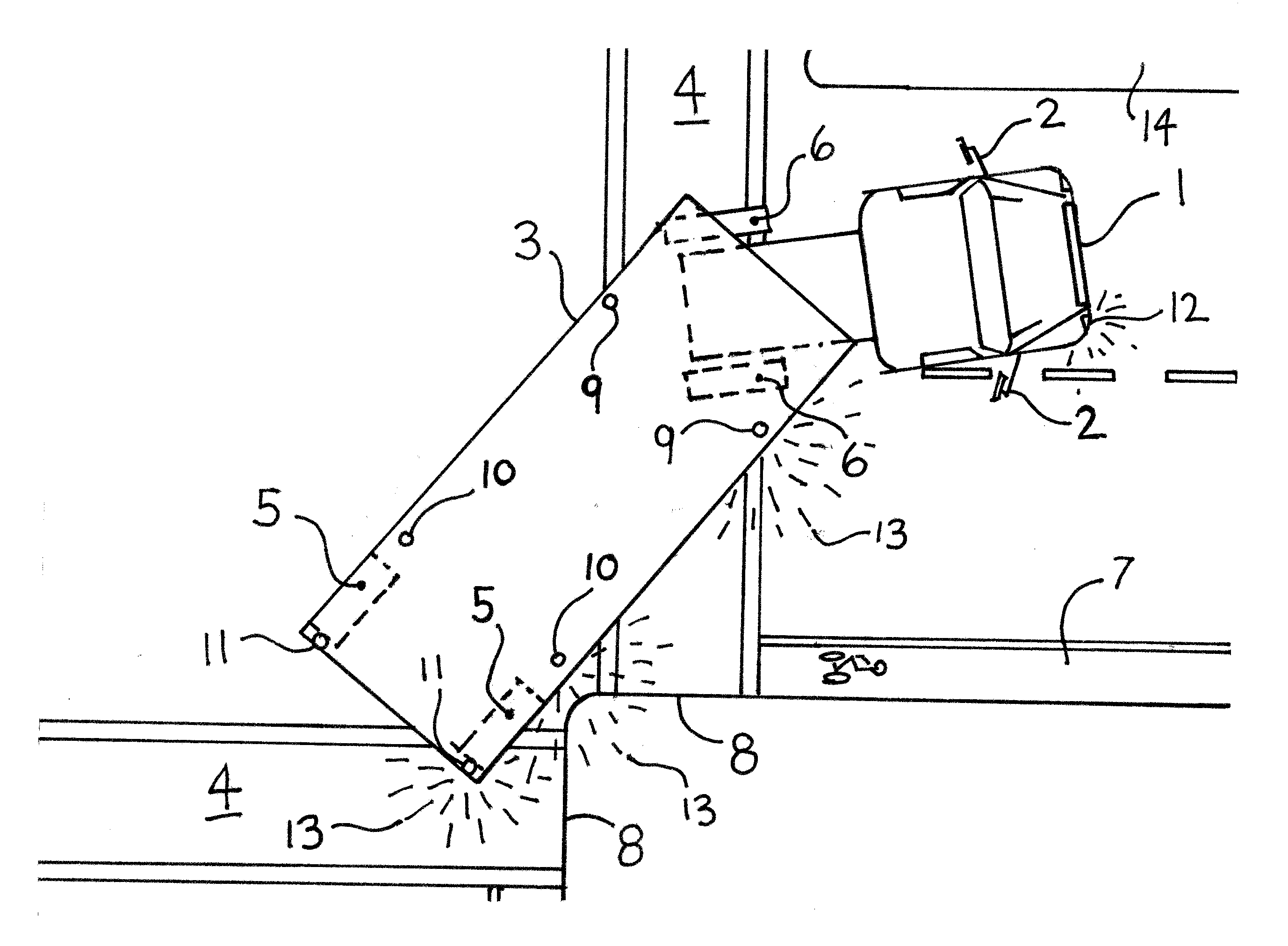
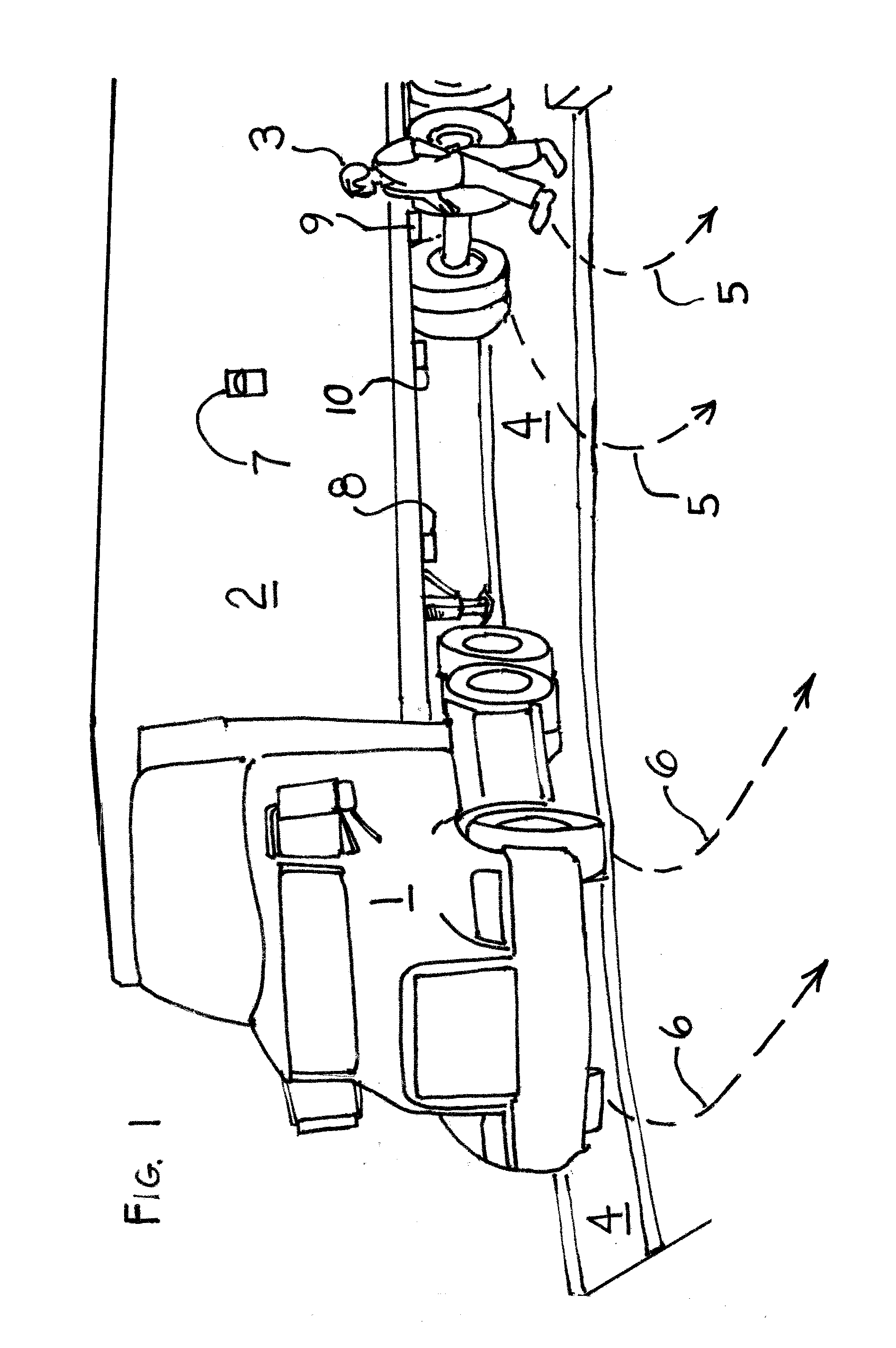
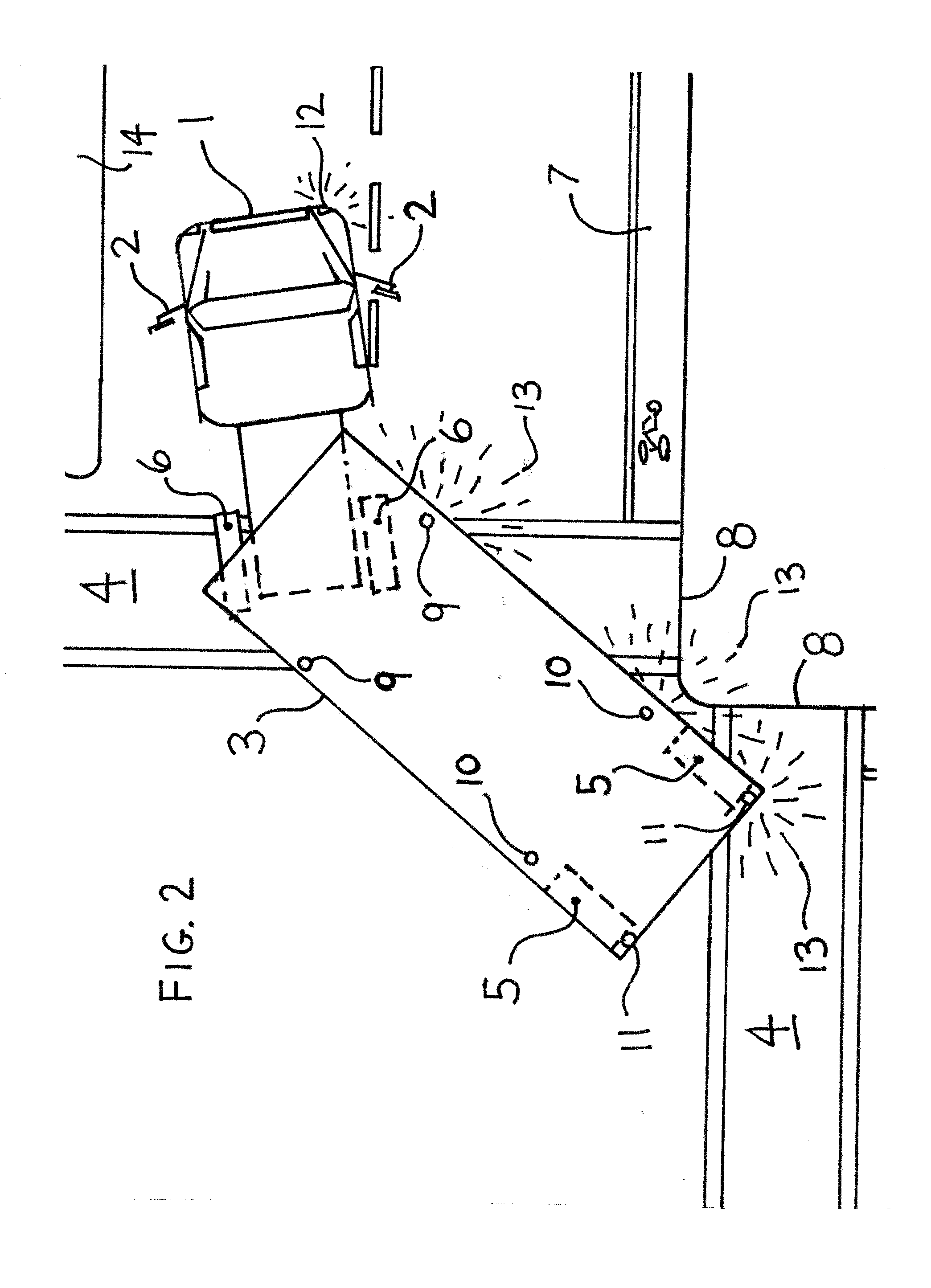
[0056]There are some symbols contained within the drawings that need to be clarified now. The presences of dashed lines that seem to be emitted from the light sources are intended to illustrate waves of light and a field of light onto the desired areas of illumination on the ground and...


PUM


Abstract

The invention describes a lighting system apparatus intended to increase safety during operation of mainly large or lengthy vehicles and combination vehicles in darkness and poor visibility. The lighting system is comprised of a single or plurality of light sources designed for vehicular use and housed in a durable thermally conductive material having a lens through which light is projected. Said light source housings are attached to the vehicle whereby, when actuated by a controller, sufficient illumination is directed onto the specific areas on the vehicle(s) and ground surface peripheral to said vehicle or combination of vehicles at one or more areas along the sides and rear or trailing portions to the extent that the driver can more safely control said vehicle(s) because of increased visual cognition of the aforementioned areas via the rear-view mirrors. Persons proximate are also more aware of said vehicle(s) position and pathway by means of said illumination and can more readily avoid dangerous contact.

Description

CROSS-REFERENCE TO RELATED APPLICATIONS[0001]Application No. 61 / 930,434 Filed on Jan. 22, 2014 by: Schotanus, Todd A. California, USATECHNICAL FIELD OF THE INVENTION[0002]This invention relates generally to safety and illumination systems for vehicles and more specifically, for improving visual cognition and control during darkness and poor visibility primarily for drivers of large and lengthy vehicles by means of illumination provided by specially positioned and controlled light sources. This invention is particularly adaptable for incorporation into or onto the bodies and / or framework of both “on-road” and “off-road” vehicles having wheels or tracks.[0003]Unlike the traditional role of headlights which are employed to illuminate what is ahead, this invention is employed primarily to improve safety by illuminating the dark areas on the road surface and peripheral space that is within the pathway or zone of the sides, rear or trailing portion of a vehicle or combination of said. The...

Claims


Application Information

Patent Timeline
Patent Type & Authority Applications(United States)
IPC IPC(8): B60Q1/24B60Q1/00F21V29/70F21K99/00
CPCB60Q1/24F21K9/50B60Q1/0005F21W2101/02B60Q1/0076F21Y2101/02F21V29/70B60Q1/0035B60Q1/0088B60Q1/0483B60Q1/2615B60Q1/305B60Q1/32B60Q1/326B60Q2800/20B60Q1/247
Inventor SCHOTANUS, TODD A
Owner SCHOTANUS TODD A
Why Eureka
Try Eureka