Poppet valve for a compressor

a technology for compressors and poppets, applied in valve housings, positive displacement liquid engines, liquid fuel engines, etc., can solve problems such as inhibition or blocking of the movement of closing elements, and deteriorating functions of the valve housing

Active Publication Date: 2015-07-23
BURCKHARDT COMPRESSION AG
View PDF1 Cites 8 Cited by
  • Summary
  • Abstract
  • Description
  • Claims
  • Application Information

AI Technical Summary

Benefits of technology

[0011]In a particularly advantageous embodiment, the bottom element and the support element are configured adapted to each other such that the passage is constantly open throughout. In a further advantageous embodiment, the bottom element and the support element are configured adapted to each other such that the passage is either open throughout or is closed partially or even completely, depending on the mutual positioning of the support element relative to the bottom element. In an advantageous embodiment, the support ...

Problems solved by technology

The poppet valve known from publication US2010/0090149 has the disadvantage that its function deteriorates after a certain operating duration, in particular when the valve is operated with a contaminated fluid, for example a g...

Method used


Image

  • Poppet valve for a compressor
  • Poppet valve for a compressor
  • Poppet valve for a compressor

Examples


Embodiment Construction

[0005]The object of the invention is to configure a poppet valve which has more advantageous operating properties.

[0006]This object is achieved with a poppet valve having the features of claim 1. Subclaims 2 to 13 concern further advantageous embodiments of the invention. The object is furthermore achieved with a repair kit for a poppet valve having the features of claim 15.

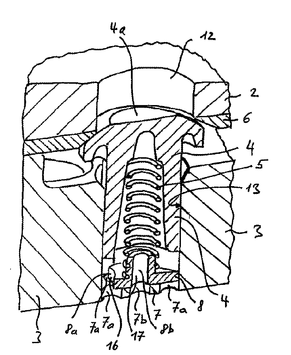
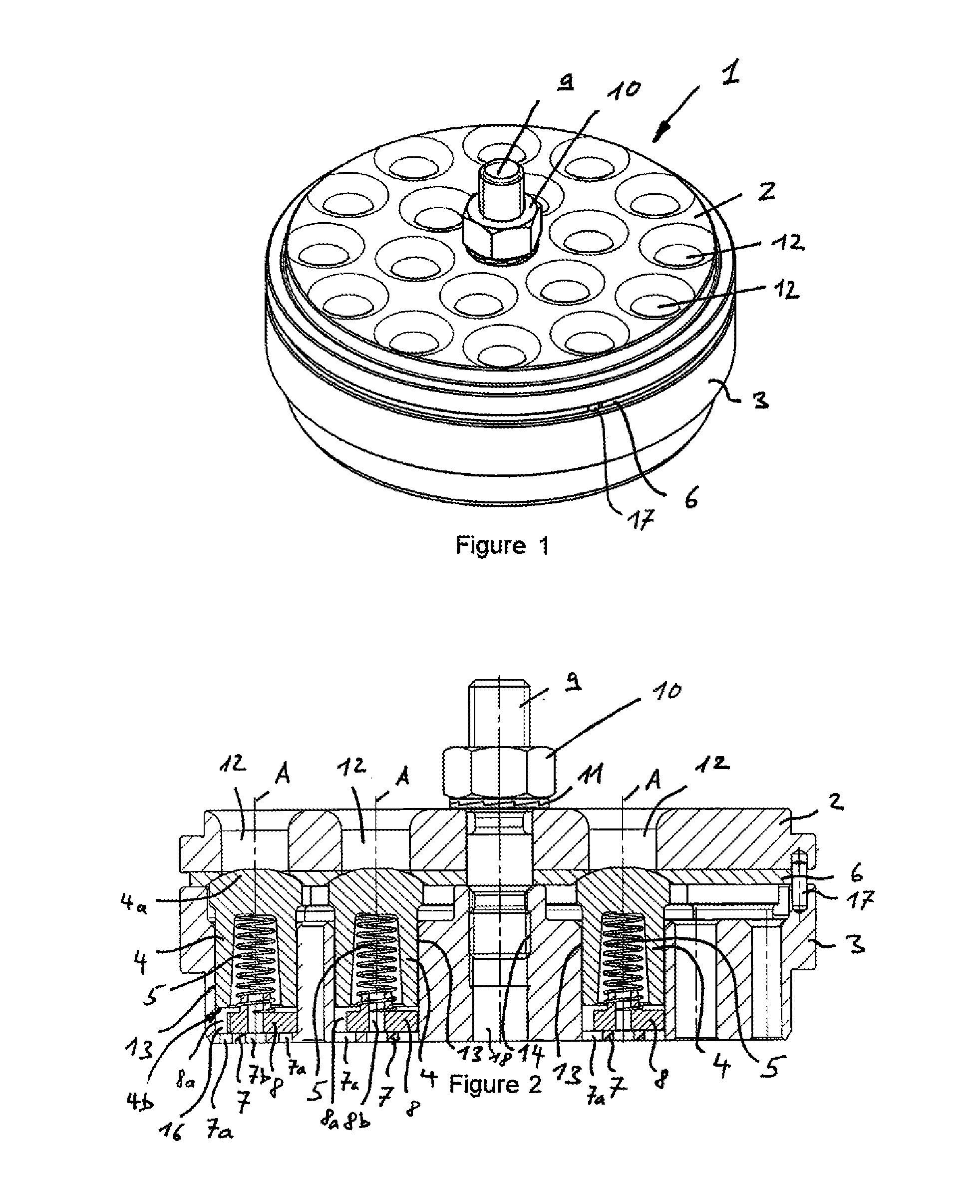
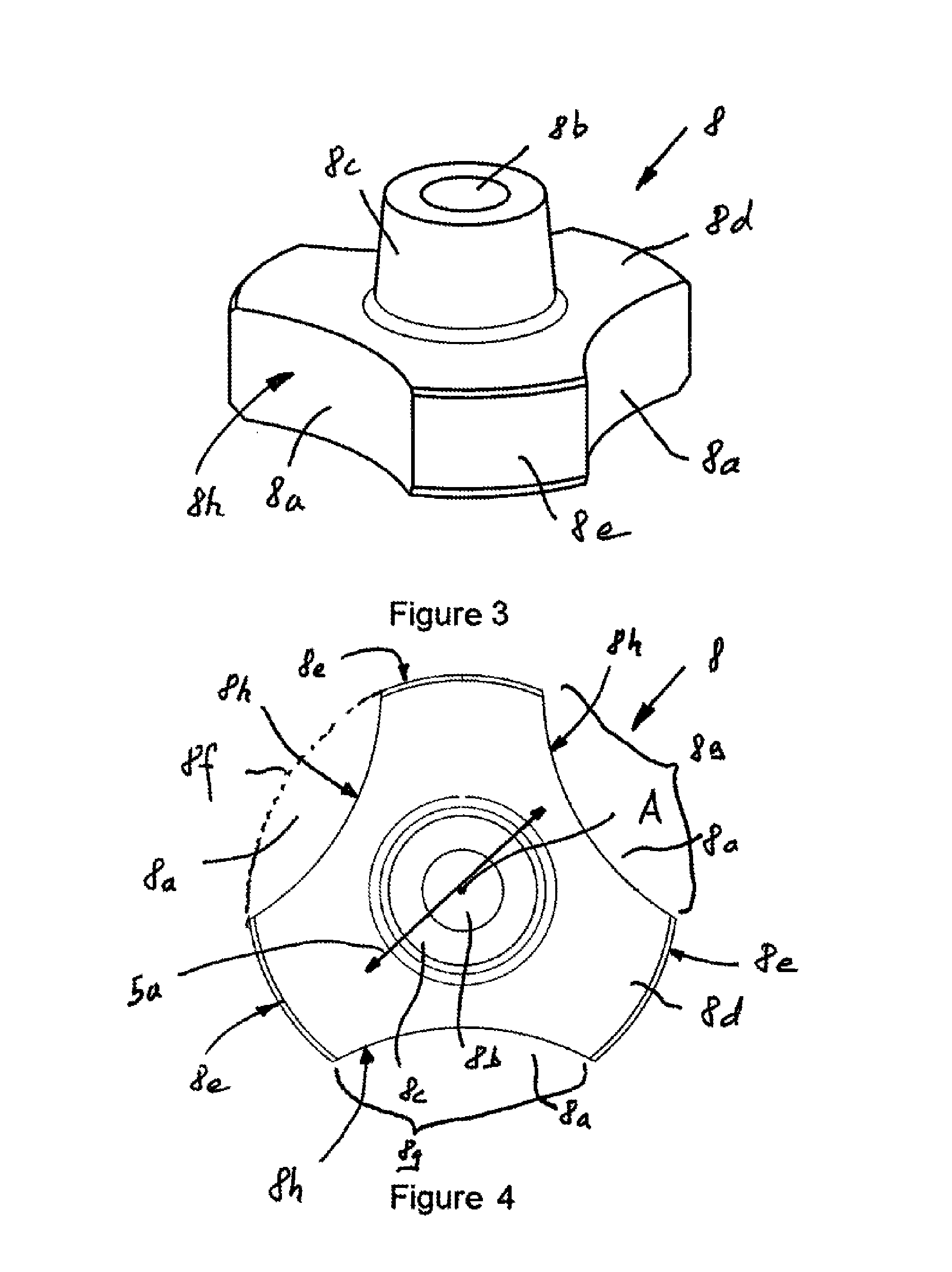
[0007]The object is achieved in particular with a poppet valve comprising a cage, a valve seat and a plurality of closing elements, wherein the cage has a plurality of bores running in an axial direction, wherein the bores are open towards the valve seat and have a bottom element at an end opposite the valve seat, wherein a closing element which is moveable in the axial direction A is arranged in each bore, wherein the valve seat has a plurality of passage openings which are arranged opposite the bores in the axial direction A such that each of the passage openings can be closed by one of the closing elements, wh...


PUM


Abstract

A poppet valve for a compressor, a piston compressor including such a poppet valve, and a repair kit for a poppet valve. The poppet valve has a cage, a valve seat and a plurality of closing elements, wherein the cage has a plurality of axial bores open towards the valve seat.

Description

[0001]The invention concerns a poppet valve for a compressor, a piston compressor comprising such a poppet valve, and a repair kit for a poppet valve.PRIOR ART[0002]Publication US2010 / 0090149 discloses a poppet valve for a compressor. This poppet valve has a cage in which a plurality of bores is produced. A closing element is arranged in each of the bores. The closing element is mushroom-shaped and has a stem and a head, the diameter of which is greater than that of the stem. The stem is held in a bore of the cage and contains a cavity in which a spring is held. At its end opposite the cavity, the spring rests on a bottom element which is arranged on the base of the bore in the cage. The head of the closing element is configured such that in the closed state it closes a bore in the valve seat plate, wherein the valve seat plate is connected to the cage via a screw connection. In the pressureless state, the closing element is held by the spring such that the bore in the valve seat pl...

Claims


Application Information

Patent Timeline
IPC IPC(8): F04B39/10F16K15/02
CPCF16K15/026F04B39/1013F04B39/1053F16K27/0209Y10T137/7933
Inventor COLUMPSI, MICHELE
Owner BURCKHARDT COMPRESSION AG
Why Eureka
Try Eureka