Luggage handle structure

a handle and luggage technology, applied in the direction of wing knobs, furniture parts, transportation and packaging, etc., can solve the problems of difficult button position and link mechanism design, difficult to push the button with the forefinger or the middle finger, etc., to achieve convenient use, simple structure, and reduce cost

Inactive Publication Date: 2015-07-30
TONG JOY
View PDF5 Cites 24 Cited by
  • Summary
  • Abstract
  • Description
  • Claims
  • Application Information

AI Technical Summary

Benefits of technology

[0009]The button of the luggage handle structure of the present invention is located at the side of the handle. This is beneficial to push the button when the user grasps th

Problems solved by technology

It is not easy to push the button with the forefinger or the middle finger when the user grasps the handle.
If the pull rod is repl

Method used


Image

  • Luggage handle structure
  • Luggage handle structure
  • Luggage handle structure

Examples


Embodiment Construction

[0016]Embodiments of the present invention will now be described, by way of example only, with reference to the accompanying drawings.

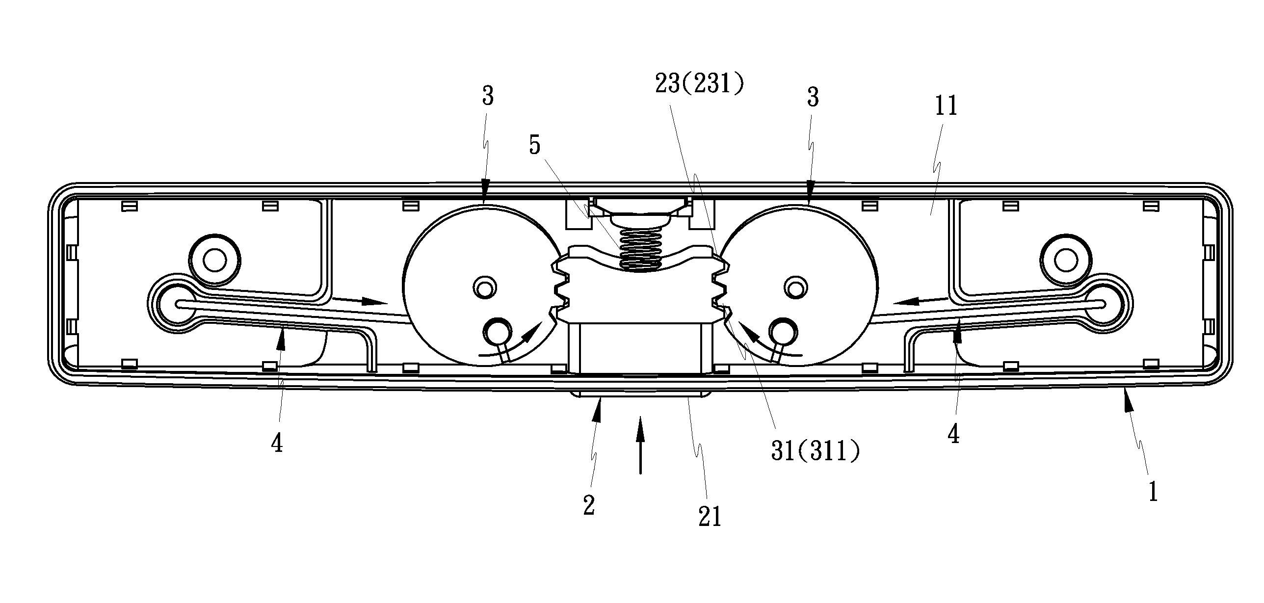
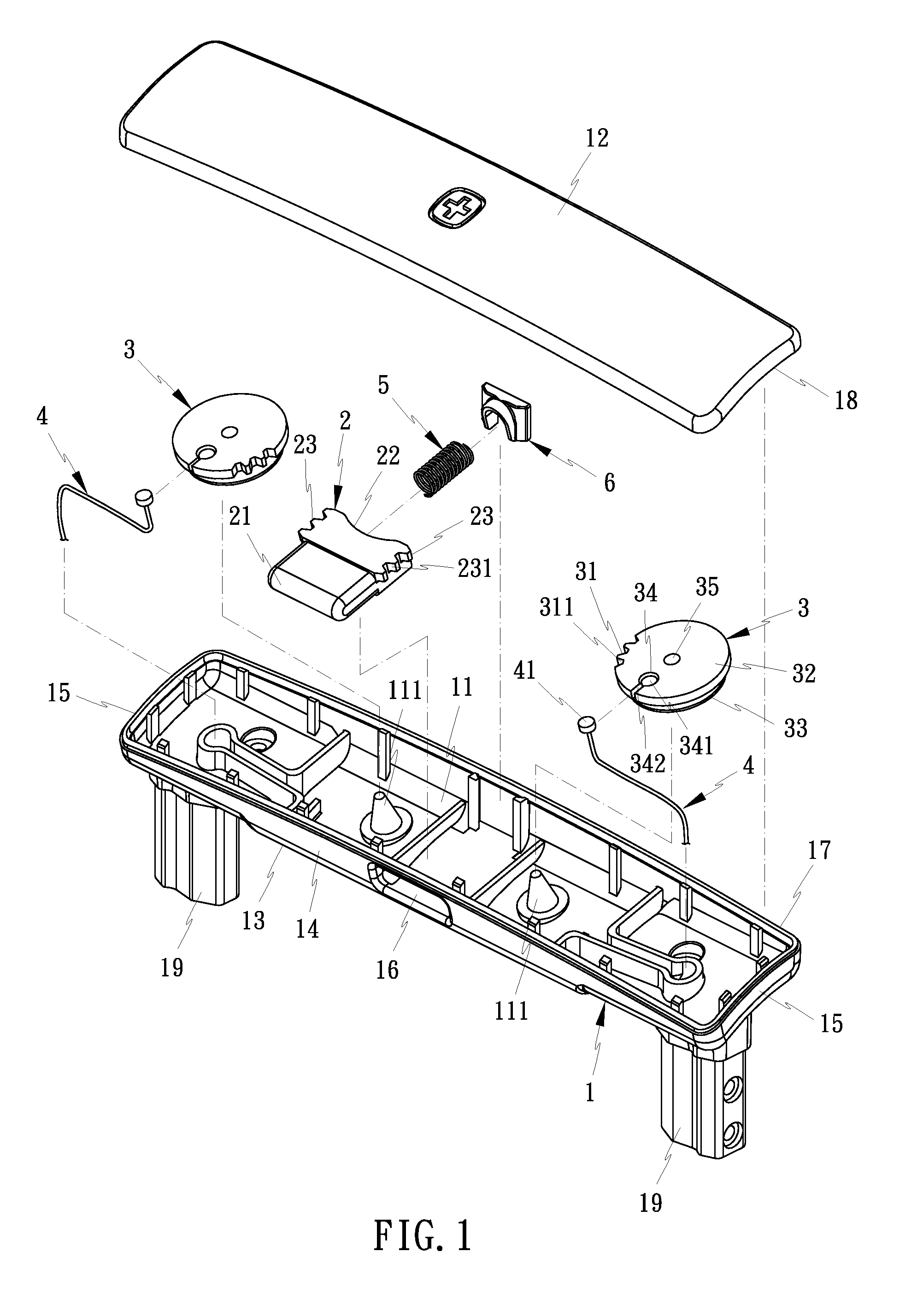
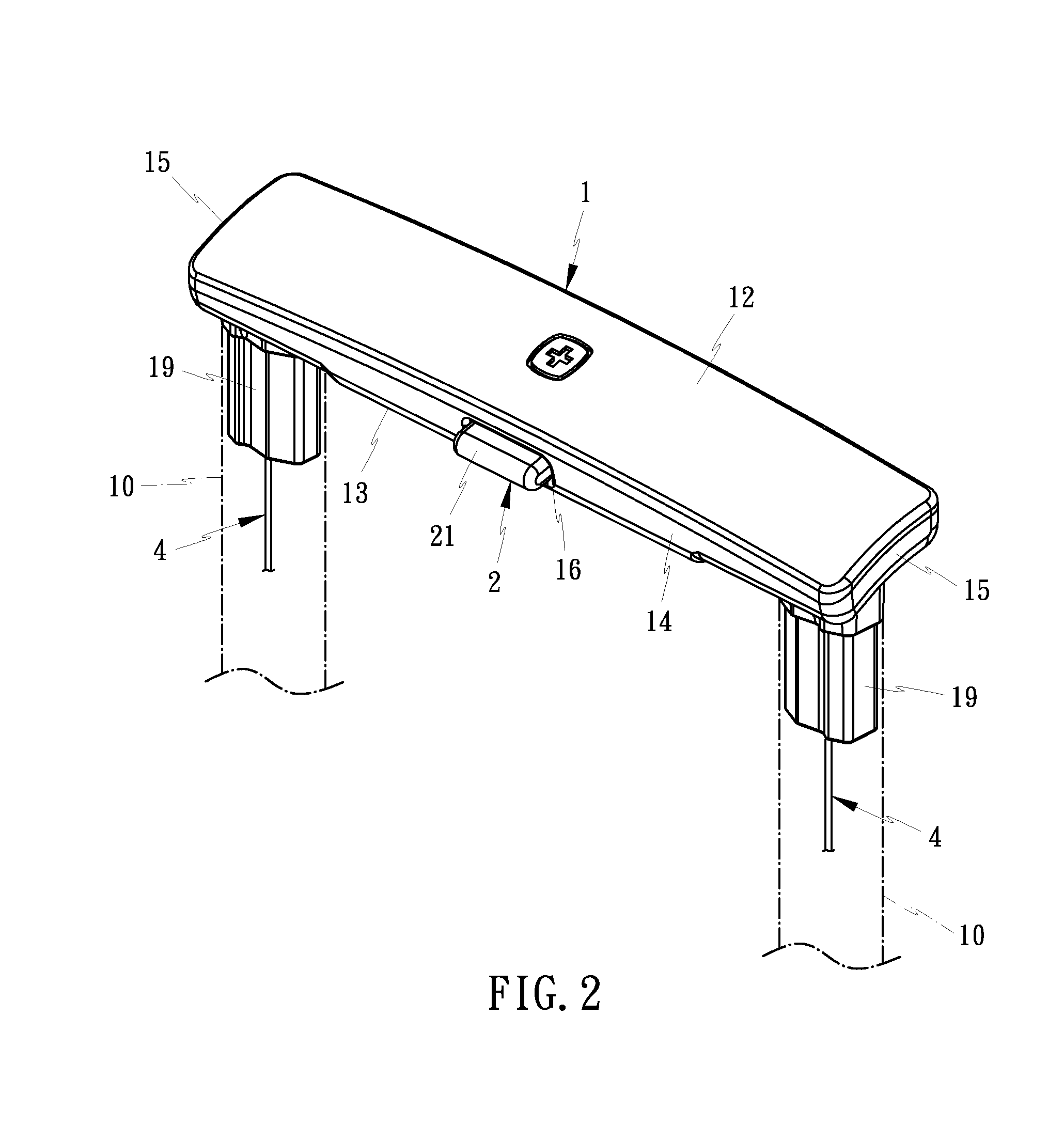
[0017]As shown in FIG. 1 and FIG. 2, the luggage handle structure of the present invention is coupled to a retractable pull rod 10 of a luggage to drive an engaging mechanism in the retractable pull rod 10. The luggage handle structure is able to control extension and retraction of the retractable pull rod 10. The luggage handle structure according to a preferred embodiment of the present invention comprises a handle 1, a button 2, a transmission member 3, and a pull rope 4. Preferably, the luggage handle structure of the present invention further comprises an elastic member 5 and a fixing member 6.

[0018]As shown in FIG. 1, the handle 1 is coupled to the upper end of the retractable pull rod 10 (as shown in FIG. 2). The handle 1 has an accommodation space 11 therein. The handle 1 has an inclined top 12, a bottom 13 opposite to the top 12, two sides 14...


PUM


Abstract

A luggage handle structure is coupled to a retractable pull rod of a luggage to control extension and retraction of the retractable pull rod. The luggage handle structure includes a handle, a button, a transmission member, and a pull rope. The handle has an accommodation space therein and a button hole at one side thereof to communicate with the accommodation space. The button is disposed in the button hole of the handle. The button has a rear end inserted into the accommodation space. The rear end has a first transmission portion. The transmission member is disposed in the accommodation space. The transmission member has a second transmission portion to mesh with the first transmission portion. The transmission member is driven by the button. One end of the pull rope is coupled to the transmission member, and another end is to bring the engaging mechanism to lock or unlock.

Description

BACKGROUND OF THE INVENTION[0001](a) Field of the Invention[0002]The present invention relates to a luggage handle structure, and more particularly to a luggage handle structure able to control extension and retraction of a retractable pull rod of a luggage.[0003](b) Description of the Prior Art[0004]In general, a luggage is provided with a retractable handle having one or two retractable pull rods. The retractable pull rod is provided with an engaging mechanism therein. When the engaging mechanism is locked, the retractable pull rod cannot be extended. When the engaging mechanism is unlocked, the retractable pull rod can be extended or retracted. The end of the retractable pull rod is coupled with a handle. The handle is provided with at least one button. The button is able to touch a link mechanism to lock or unlock the engaging mechanism, such that the user can extend or retract the extractable pull rod as desired.[0005]However, the button of the handle applied to the retractable...

Claims


Application Information

Patent Timeline
IPC IPC(8): A45C13/26
CPCA45C2013/267A45C13/26
Inventor TONG, JOY
Owner TONG JOY
Why Eureka
Try Eureka