Low Pressure Fogging Device

a fogging device and low pressure technology, applied in spray nozzles, climate change adaptation, agriculture, etc., can solve the problems of loss of nozzle functionality, difficult cleaning of nozzles, and difficult disassembly and assembly of nipples

Active Publication Date: 2015-07-30
SHIN HONG KUN
View PDF6 Cites 2 Cited by
  • Summary
  • Abstract
  • Description
  • Claims
  • Application Information

AI Technical Summary

Benefits of technology

[0008]Accordingly, the present invention has been made in view of the above-mentioned problems occurring in the prior art, and it is an object of the present invention to provide a low pressure fogging device that is capable of allowing a fluid flow-inducing member and a nozzle body laid on top of a fogging device body to be mechanically contacted with each other by means of a push-up nut screw-coupled to the fogging device body, without having any separate tool, thus maintaining complete tightness, filtering foreign matters in sequential steps when a fluid is passed through the fluid flow-inducing member from the fogging device body to minimize the occurrence of clogging on passages, allowing the depths of the passages formed on the outer peripheral surface of the fluid flow-inducing member to be equal to or smaller than the diameter of a nozzle hole to prevent the nozzle hole from clogging, increasing the number of spraying times without clogging on the nozzle hole, maintaining the fogging capability at a low pressure (in the range of 2 to 3 kg / cm2), and conducting easy cleaning.

Problems solved by technology

In the above-mentioned prior art, however, the nipple is screw-coupled to the nozzle fixture in such a manner as to be embedded into the nozzle fixture, thus making it hard to disassemble and assemble the nipple.
Besides, the passages formed on the nipple are large to cause foreign matters passed therethrough to clog the nozzle hole, thus making the functionality of the nozzle lost, and further, it is hard to clean the nozzle, thus making the fogging device itself thrown away.

Method used


Image

  • Low Pressure Fogging Device
  • Low Pressure Fogging Device
  • Low Pressure Fogging Device

Examples


first embodiment

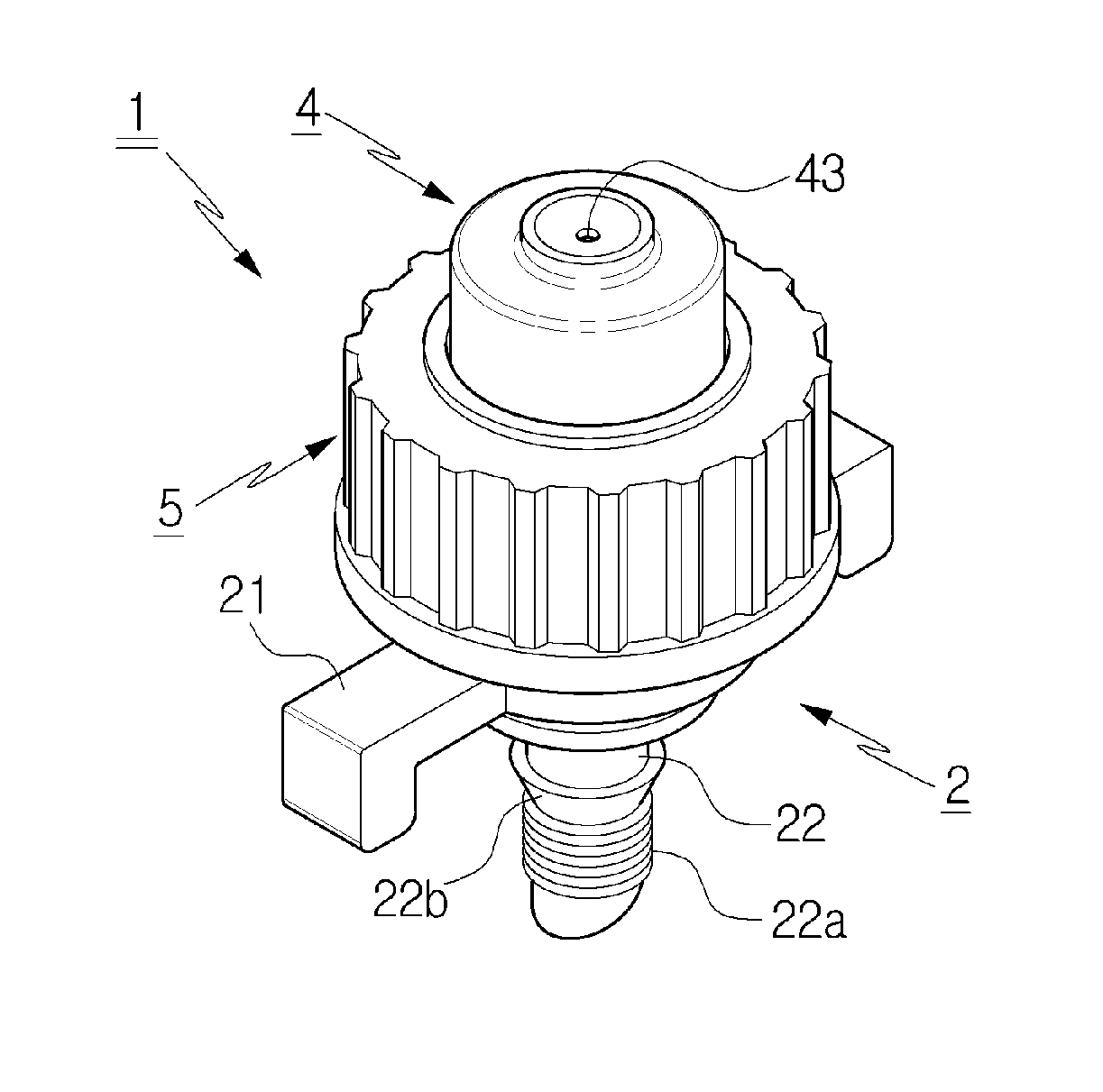
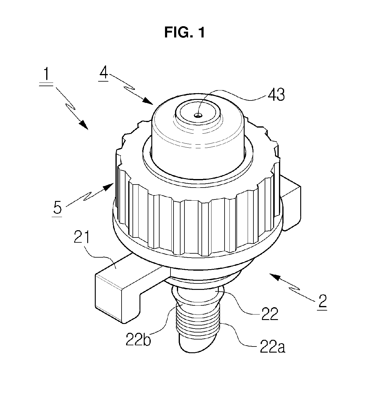
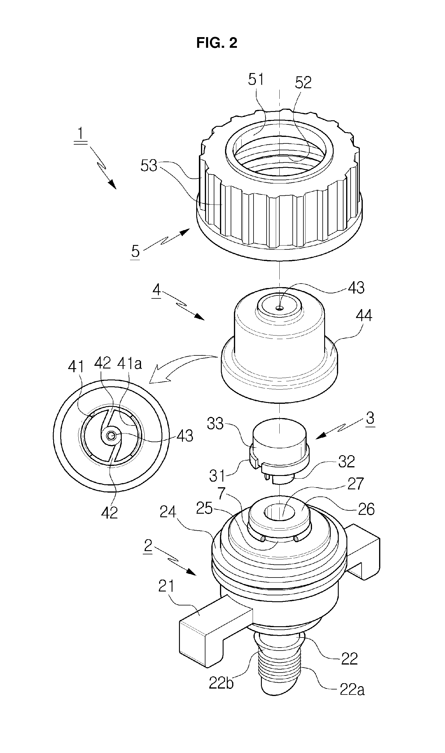
[0030]As shown, a low pressure fogging device 1 according to the present invention largely includes a fogging device body 2, a fluid flow-inducing member 3 mounted on top of the fogging device body 2, a nozzle body 4 adapted to close the upper portion of the fluid flow-inducing member 3, and a push-up nut 5 screw-coupled to the fogging device body 2 to pressurize the nozzle body 4 toward the fluid flow-inducing member 3.

[0031]The fogging device body 2 has a hose coupling tube 22 formed unitarily with the lower side thereof around a boundary flat plate 21. The hose coupling tube 22 includes a screw tube 22a formed on the lower periphery thereof in such a manner as to be screw-coupled to a hose 6 and an inversely tapered barb 22b formed on the upper periphery thereof in such a manner as to be increased in diameter as it goes toward the upper side thereof, and accordingly, the hose coupling tube 22 is assembled to the hose 6 having various diameters. That is, if the hose 6 has a diamet...

second embodiment

[0044]According to the present invention, the fluid flow-inducing member 3 has a body 35 inserted into the nozzle body 4 in such a manner as to come into close contact with the vortex passages 42 and a plurality of base protrusions 36 formed radially on the lower end periphery of the body 35 in such a manner as to be seated on the top of the fluid flow-inducing member seating plate 26, thus forming a space portion P between the fluid flow-inducing member seating plate 26 and the base protrusions 36 to conduct fluid movement. At this time, the body 35 has a fitting portion 35a formed on the top portion thereof in such a manner as to be reduced in diameter, and the fitting portion 35a is fitted to the coupling protrusions 41a formed on the nozzle body 4 to allow the top surface thereof to be face-contacted with the vortex passages 42 formed on the nozzle body 4. Further, a cylindrical passage 37 is formed between the outer peripheral surface of the fluid flow-inducing member 3 and the...


PUM


Abstract

A low pressure fogging device includes a fogging device body having a hose coupling tube formed unitarily with the lower side thereof, a screw portion formed on the upper side thereof, and a fluid flow-inducing member seating plate formed on top of the screw portion; a fluid flow-inducing member having induction wings seated on top of the fluid flow-inducing member seating plate; a nozzle body having a fitting hole open downwardly therefrom to allow the fluid flow-inducing member seating plate and the fluid flow-inducing member to be fitted thereto; and a push-up nut having a pressuring ring formed at the center thereof to be locked onto a locking projection formed from an outer lower end periphery of the nozzle body and a screw groove formed at the inner periphery thereof to be fastened to a screw portion formed on the fogging device body.

Description

REFERENCE TO RELATED APPLICATIONS[0001]This application claims the priority benefit of Korean Patent Application No. 10-2014-0011756 filed on Jan. 29, 2014, and Korean Patent Application No. 10-2014-0182526 filed on Dec. 18, 2014, the entire contents of which are incorporated herein by reference.FIELD OF THE INVENTION[0002]The present invention relates to a low pressure fogging device that is applied to a green house or barn to spray fine water drops like fog, and more particularly, to a low pressure fogging device that is assemblable and disassemblable, without having any separate tool, maintains complete tightness through screw type mechanical combination, minimizes the decrement of pressure of a fluid, conducts easy cleaning, filters foreign matters in sequential steps when the fluid is passed through a fluid flow-inducing member from a fogging device body to minimize the occurrence of clogging on passages, allows the depths of the passages of the fluid flow-inducing member to be...

Claims


Application Information

Patent Timeline
Patent Type & Authority Applications(United States)
IPC IPC(8): B05B1/02
CPCB05B1/02B05B1/14B05B1/3436A01G9/247Y02A40/25
Inventor SHIN, HONG KUN
Owner SHIN HONG KUN
Why Eureka
Try Eureka