AI technical title is built by Patsnap AI team. It summarizes the technical point description of the patent document.
a technology of actuators and boats, applied in vessel parts, special-purpose vessels, vessel construction, etc., can solve the problems of affecting people's climbing in and out of the side of the boat, affecting the aesthetics of the stowed position, and increasing the wind resistance, so as to achieve easy leveling and wide stance. the effect of the boa
Active Publication Date: 2015-07-30
HEWITT MACHINE & MFG
View PDF2 Cites 2 Cited by
Summary
Abstract
Description
Claims
Application Information
AI Technical Summary
This helps you quickly interpret patents by identifying the three key elements:
Problems solved by technology
Method used
Benefits of technology
Benefits of technology
The present invention is an onboard lift for lifting a boat. The lift has two moveable legs that can be raised and lowered. The legs have slide feet that allow the boat to slide on the ground surface. This makes it easier to level the boat when lifted over a sloped grade. The lift also has a control that can display the front and rear support structures separately, making it easier for operators to adjust the boat's level.
Problems solved by technology
At the same time, however, the stowed position detracts aesthetically from the appearance of the boat during use, and increases wind resistance during use of the boat.
The stowed position of the legs and pads can also interfere with people climbing in and out of the side of the boat.
However, the narrow base creates a potentially unstable stand for the pontoon boat when raised, and a stiff wind, particularly if coupled with angled placement or loading of the boat, could create a potentially dangerous or damaging possibility of tipping or flipping the boat off of the narrow base.
The legs and pads cannot be viewed during deployment, making deployment more difficult.
The drive systems for the legs, and particularly the independent, screw drives of the Derner system, increase the cost of the system.
Method used
Image
Click on the blue label to locate the original text in one second.
Reading with bidirectional positioning of images and text.
Examples
Embodiment Construction
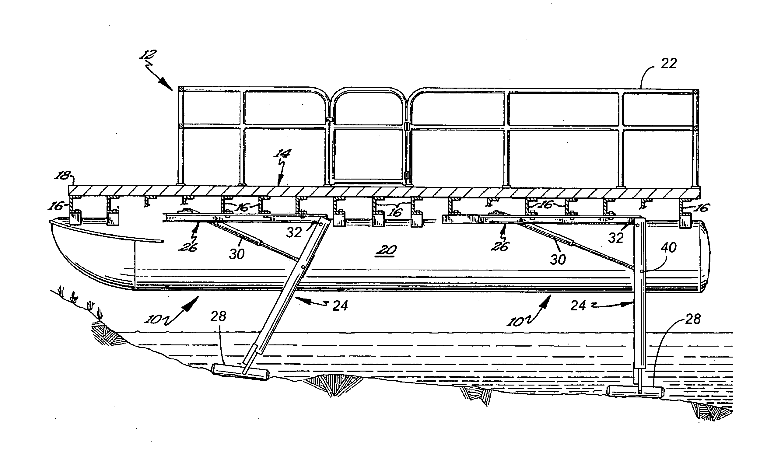
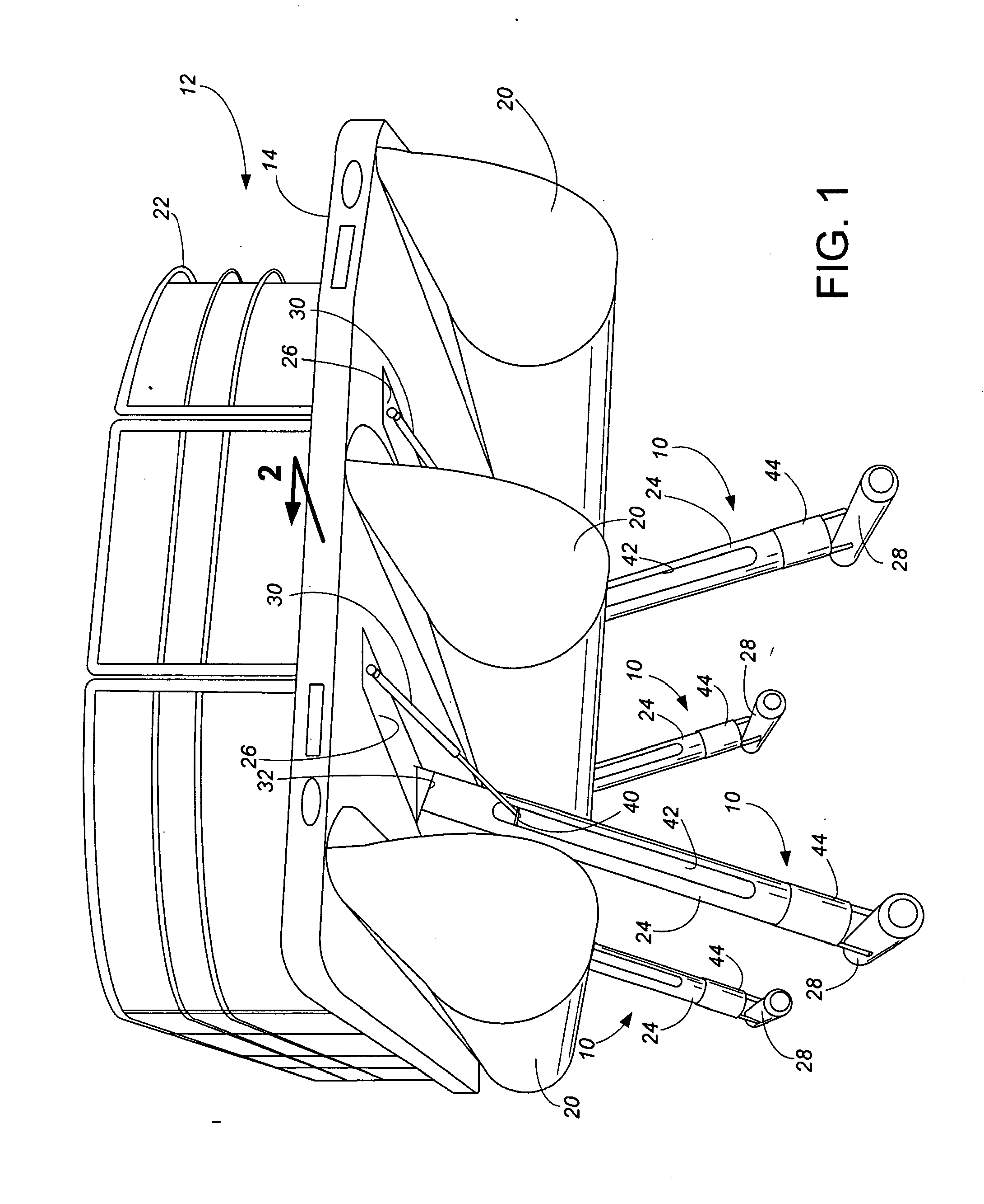
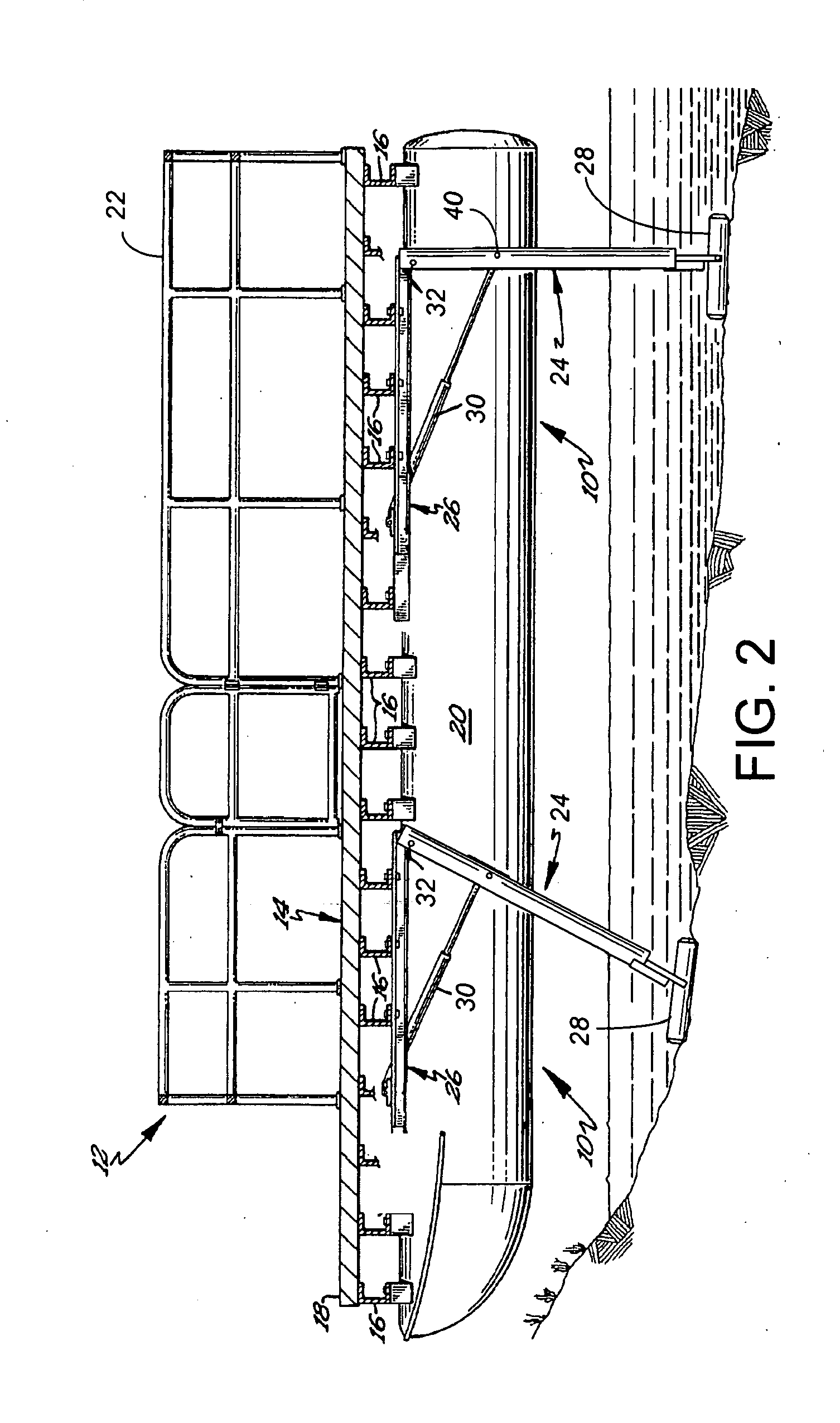
[0013]A lift for watercraft and especially pontoon boats according to the preferred teachings of the present invention is shown in the drawings and generally includes at least two and more preferably four support structures 10. A pontoon boat 12 generally includes a platform 14, which can be formed as shown in FIG. 2 with a plurality of cross members 16 supporting suitable deck material 18. The pontoon boat 12 further generally includes two or more spaced, parallel, flotation units or pontoons 20 positioned underneath the platform 14. A railing 22 normally extends above the platform 14. An outboard motor (not shown) is normally mounted at the rear of platform 14.
[0014]In the preferred embodiment, each support structure 10 primarily includes a leg 24 extending from a mount 26 to a slide foot 28, and a power mechanism 30 for operating the support structure 10. Each mount or attachment bracket 26 is suitably secured such as with bolts (not shown) to an attachment surface on the undersi...
PUM
Abstract
An onboard lift for a pontoon boat has four legs pivotally attached underneath a platform and extending between the outer pontoons. Each leg terminates in a slide foot. The pivot pin for each leg is canted, such as at 13° relative to horizontal. In a stowed position, the legs and slide feet extend forward in the direction of travel and tight to the platform. When used to lift the boat, actuation of the legs pushes the slide feet outward due to the cant of the pivot axis, such that the slide feet are positioned underneath the outer pontoons when the boat is fully raised. The control allows separate powering of the front legs from the rear legs, and further has a display so the user can see the amount of extension of each set of legs.
Description
CROSS-REFERENCE TO RELATED APPLICATION(S)[0001]This application claims priority from Provisional Application No. 61 / 037,711, filed Mar. 19, 2008, entitled POWER FOR ONBOARD BOAT LIFT, and from Provisional Application No. 61 / 037,712, filed Mar. 19, 2008, entitled ONBOARD BOAT LIFT STRUCTURE, both incorporated herein by reference.BACKGROUND OF THE INVENTION[0002]The present invention relates to boat lift structures for raising and supporting boats, and more particularly to boat lift structures which are carried onboard during use of the boat. Examples of such prior art onboard boat lift structures are provided in U.S. Pat. No. 5,042,417 to Raymond, U.S. Pat. No. 5,558,034 to Hodapp, and in a series of patents (U.S. Pat. Nos. 6,907,835, 6,983,707, 7,051,665, 7,156,030, 7,267,066 and 7,318,385) to Derner et al. All these mentioned patents are incorporated by reference.[0003]In general terms, these existing onboard lift structures involve a plurality of legs which are pivotable relative ...
Claims
Application Information
Patent Timeline
Application Date:The date an application was filed.
Publication Date:The date a patent or application was officially published.
First Publication Date:The earliest publication date of a patent with the same application number.
Issue Date:Publication date of the patent grant document.
PCT Entry Date:The Entry date of PCT National Phase.
Estimated Expiry Date:The statutory expiry date of a patent right according to the Patent Law, and it is the longest term of protection that the patent right can achieve without the termination of the patent right due to other reasons(Term extension factor has been taken into account ).
Invalid Date:Actual expiry date is based on effective date or publication date of legal transaction data of invalid patent.
Patent Type & AuthorityApplications(United States)

