Liquid crystal display device

a liquid crystal display and display device technology, applied in non-linear optics, instruments, optics, etc., can solve the problems of easy damage, double image phenomenon, deterioration of image quality, etc., and achieve the effect of lowering the contrast at the periphery of the screen and improving the brightness of the screen

Inactive Publication Date: 2015-07-30
JAPAN DISPLAY INC
View PDF5 Cites 6 Cited by
  • Summary
  • Abstract
  • Description
  • Claims
  • Application Information

AI Technical Summary

Benefits of technology

The present invention is about a liquid crystal display device with a front window. The device prevents light from the backlight or external light from entering the periphery of the front window, which can deteriorate the contrast of the screen. This is achieved by using an adhesive with a refractive index close to that of glass, which shields the area around the front window and prevents light leakage. Even when the screen is viewed from an angle, the device provides excellent contrast.

Problems solved by technology

The upper polarizing plate is formed of resin so it is easily damaged.
The double image phenomenon deteriorates image quality.
On the other hand, the liquid crystal display panel involves a problem that light reflected at an end face of the TFT substrate 10 and the counter substrate 20 is emitted from the display area, thereby lowering contrast of the screen.
However, JP-A No. 2003-5160 has no disclosure related to front windows, and no description is made for light leakage at a periphery of an image screen equipped with a front window.

Method used


Image

  • Liquid crystal display device
  • Liquid crystal display device
  • Liquid crystal display device

Examples


embodiment 1

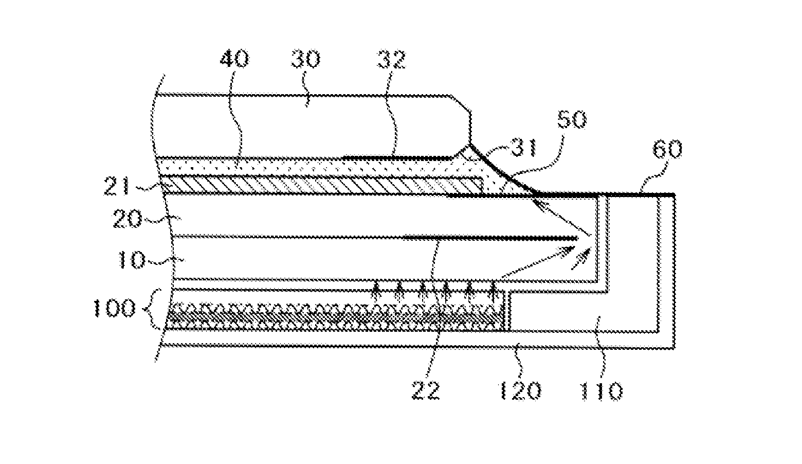
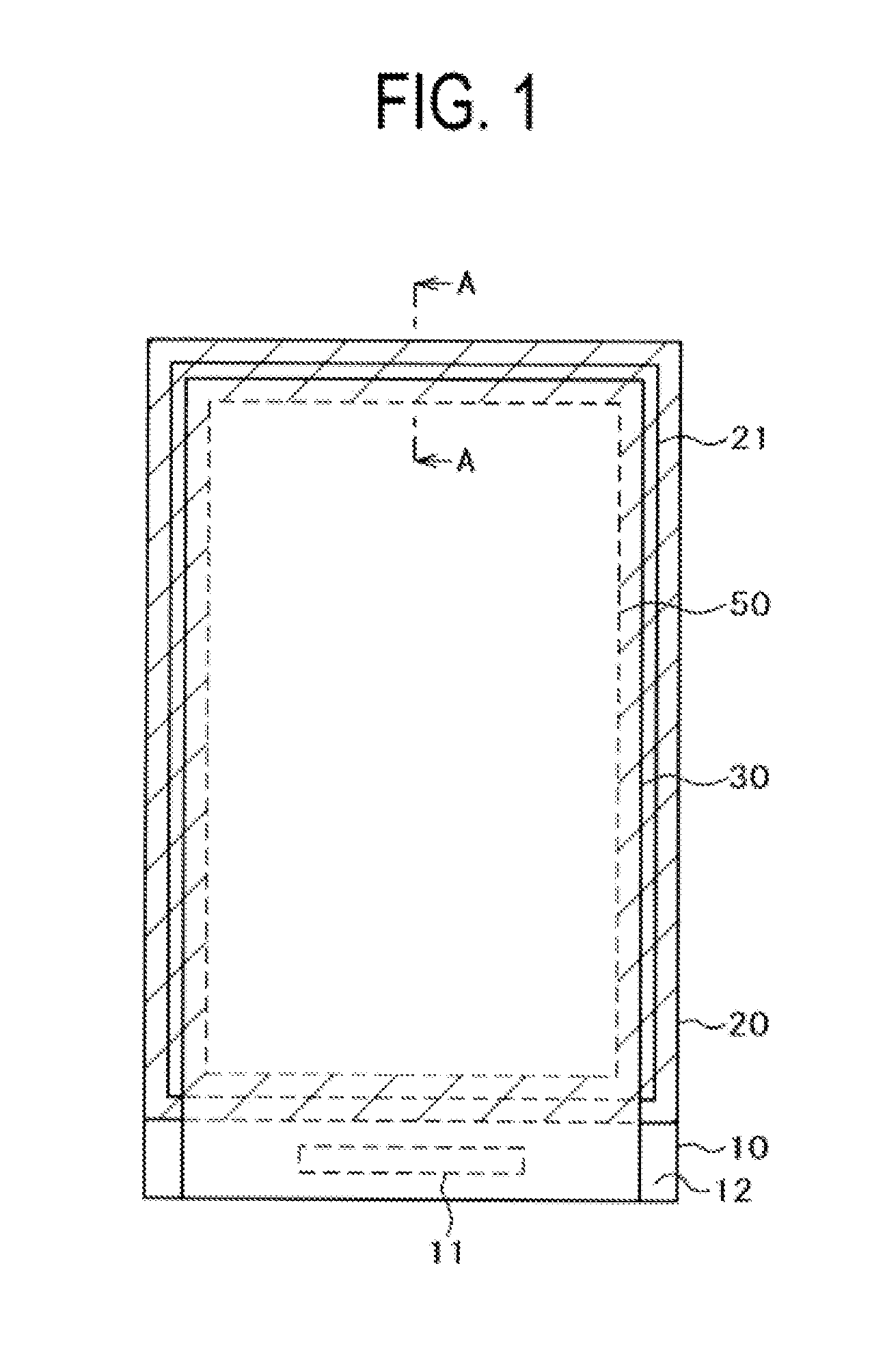
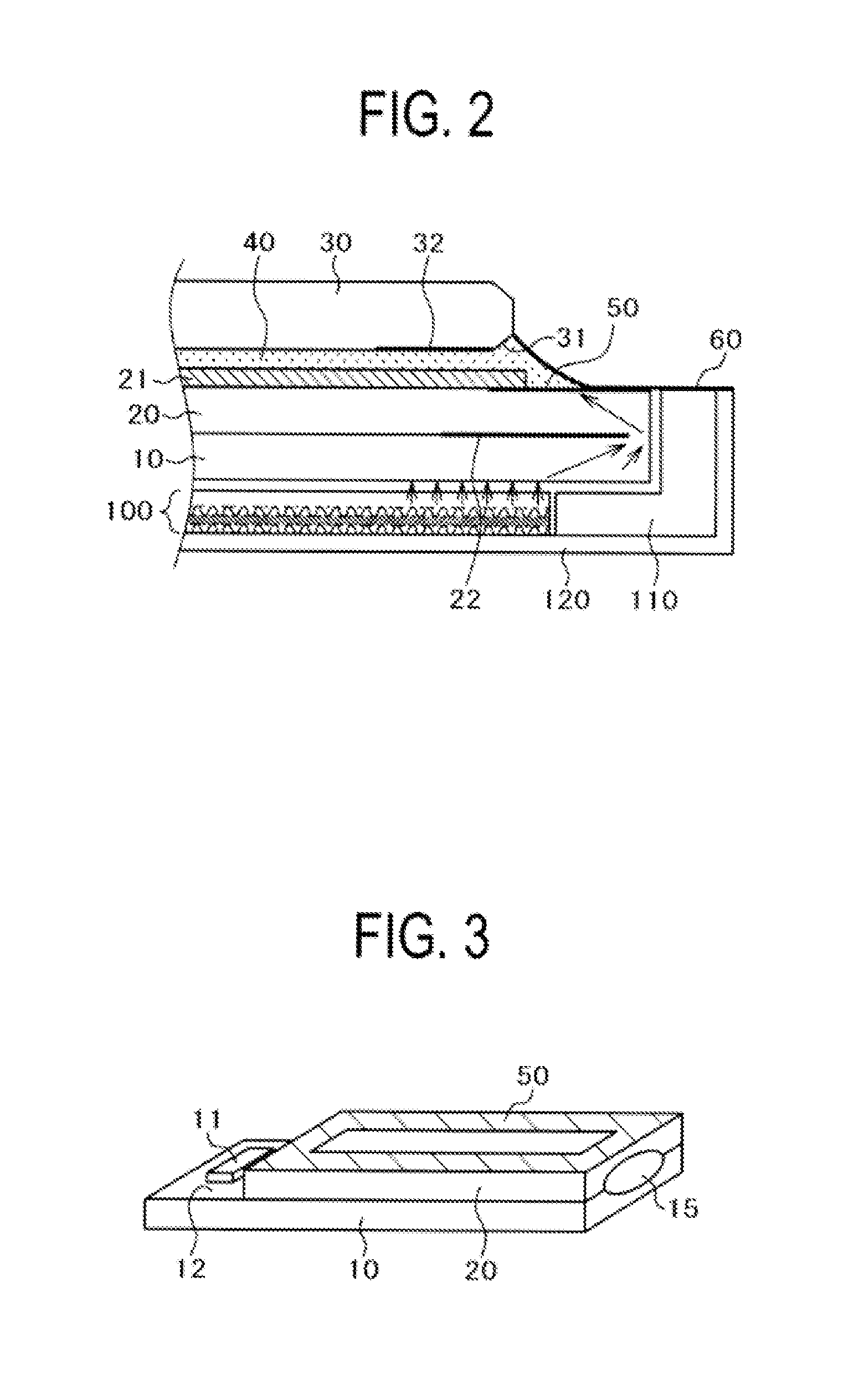
[0035]FIG. 1 is a plan view showing a first embodiment of the present invention and FIG. 2 is a cross sectional view taken along line A-A in FIG. 1 including a mold and a lower frame. In FIG. 1, a liquid crystal display panel comprises a TFT substrate 10 and a counter substrate 20. A lower polarizing plate (not illustrated) is bonded to the TFT substrate 10, and an upper substrate 21 is bonded over the counter substrate 20. A backlight 100 is disposed below the TFT substrate 10. The TFT substrate 10 is larger than the counter substrate 20, and a portion where the TFT substrate 10 is larger is a terminal portion 12 on which an IC driver 11, etc. are disposed.

[0036]A front window 30 formed of glass is bonded over the liquid crystal panel and the upper polarizing plate 21. In FIG. 1, three of the sides of the liquid crystal display panel except the side for the terminal portion 12 have an outer shape smaller than that of the liquid crystal display panel. Further, three of the sides of ...

embodiment 2

[0049]FIG. 4 is a plan view showing a second embodiment of the present invention. In FIG. 4, a liquid crystal display panel comprises a TFT substrate 10 and a counter substrate 20. An upper polarizing plate 21 is bonded by a pressure sensitive adhesive over the counter substrate 20, and a lower polarizing plate (not illustrated) is bonded to the backlight side surface of the TFT substrate 10. The TFT substrate 10 is formed larger than the counter substrate 20. The larger portion (the protruding portion) of the TFT substrate 10 is a terminal portion 12 on which an IC driver 11, etc. are disposed.

[0050]A front window 30 formed of glass is bonded over the liquid crystal display panel and the upper polarizing plate 21. In FIG. 4, the three sides of the front window 30 except the side of the terminal portion 12 have a smaller outer shape (are longer) than those of the liquid crystal display panel. In addition, the three sides of the upper polarizing plate 21 except the side of the termin...


PUM

PropertyMeasurementUnit
view angle θ2aaaaaaaaaa
angleaaaaaaaaaa
light shieldingaaaaaaaaaa

Abstract

Light emitted by a backlight can be prevented from leaking through a chamfered portion of a front window of a liquid crystal display device. An upper polarizing plate is bonded over the counter substrate, and a front window is bonded over the upper polarizing plate with a UV-curable resin adhesive. The front window is chamfered and a light shielding member is formed on the chamfered portion. The UV adhesive exists between the chamfered portion and the surface of the upper polarizing plate or the counter substrate, and an outer end of the polarizing plate exists at a point outer than an outer end of the front window. Since the light shielding member for the chamfered portion is formed, light from the backlight does not penetrate from the chamfered portion. Thus, light leakage at a periphery of a screen can be prevented even when the view angle is large.

Description

CLAIM OF PRIORITY[0001]The present application is a continuation of U.S. patent application Ser. No. 13 / 361,086, filed Jan. 30, 2012, the entire disclosure of which is hereby incorporated herein by reference, and which claims priority from Japanese Patent Application JP 2011-026329 filed Feb. 9, 2011, the content of which is hereby incorporated by reference into this application.BACKGROUND OF THE INVENTION[0002]1. Field of the Invention[0003]The present invention relates to liquid crystal display devices, and more particularly relates to a technique for improving strength and visibility of small-sized display devices used for digital steel cameras and mobile phones.[0004]2. Description of the Related Art[0005]A liquid crystal display panel includes a TFT substrate, a counter electrode opposing the TFT substrate, and liquid crystals put between the TFT substrate and the counter substrate. The TFT substrate has thin film transistors (TFT), etc. formed thereon in a matrix form. The cou...

Claims


Application Information

Patent Timeline
Patent Type & Authority Applications(United States)
IPC IPC(8): G02F1/1335G02F1/1333G02F1/1368
CPCG02F1/133602G02F1/1368G02F2001/133331G02F1/133512G02F1/133308G02F1/133528G02F2201/08G02F1/133331
Inventor HARAYAMA, TAKESHIYOSHIMOTO, TAKASHIISHII, KATSUHIKOKOBAYASHI, SETSUOISHII, AKIRATANABE, SHINJISENTO, KIYOSHI
Owner JAPAN DISPLAY INC
Why Eureka
Try Eureka