Intelligent Monitoring System
a monitoring system and intelligent technology, applied in the field of intelligent monitoring system, can solve the problems of insufficient healthcare assistants and a large amount of manpower, and achieve the effect of minimizing the inconvenience caused by the temperature measurement of the cared person
- Summary
- Abstract
- Description
- Claims
- Application Information
AI Technical Summary
Benefits of technology
Problems solved by technology
Method used
Image
Examples
first embodiment
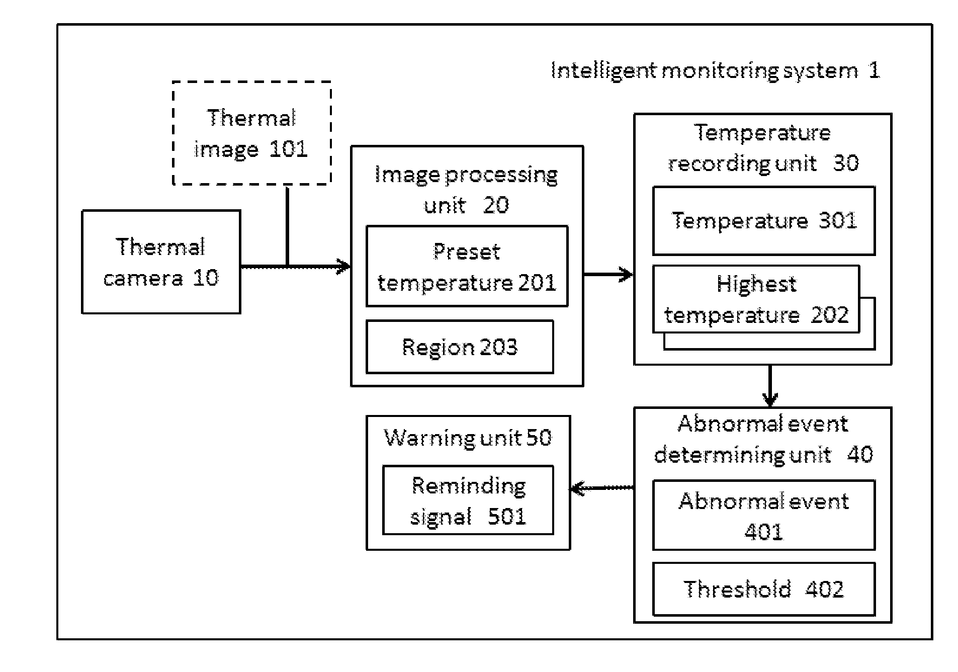
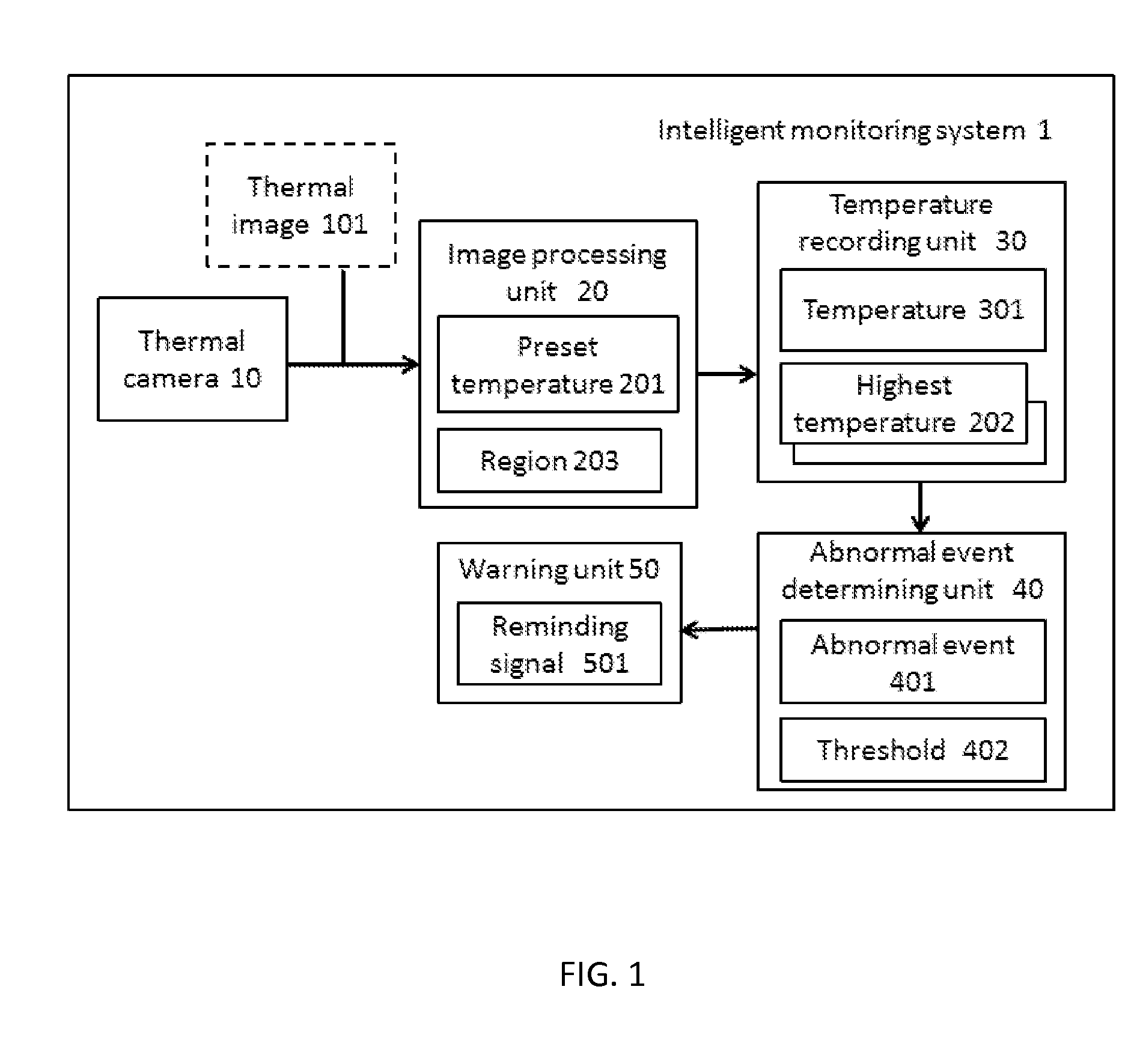
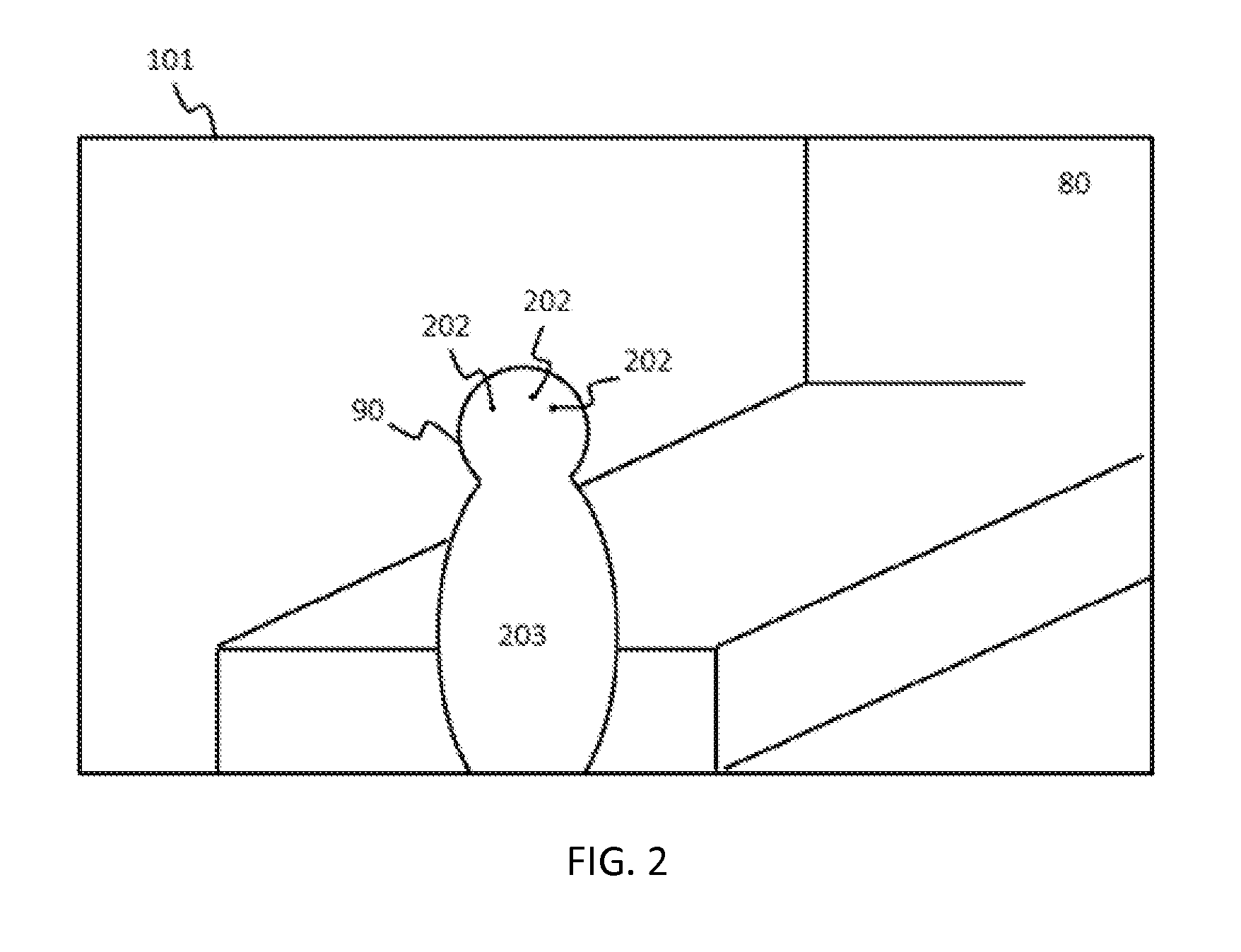
[0038]Refer to FIG. 1 and FIG. 2 which are block diagram and schematic view of a first embodiment according to the present disclosure, respectively. An intelligent monitoring system adapted for a care place 80, and comprises a thermal camera 10, an image processing unit 20, a temperature recording unit 30, an abnormal event determining unit 40 and a warning unit 50.
[0039]The thermal camera 10 captures a thermal image 101 of the care place 80. The thermal camera 10 is calibrated already, so each pixel within the thermal image 101 can correspond to a temperature value. Generally, the temperature of human body is higher than that of environment in the care place 80, so the image processing unit 20 can determine position of the user 90 in the care place 80 according to a region 203 in which the temperature is higher than a preset temperature 201 in the thermal image 101. In addition, the area or shape of the region 203 can be used for determination, to filter a coffee, a heater or food ...
second embodiment
[0047]Refer to FIG. 1 and FIG. 4 which are block diagram and schematic view of a second embodiment according to the present disclosure, respectively. The intelligent monitoring system 2 comprises a thermal camera 10, an image processing unit 20, a face identification unit 70, a temperature recording unit 30, an abnormal event determining unit 40 and a warning unit 50. The thermal camera 10 can capture a thermal image 101 of the care place 80. The image processing unit 20 can determine a position of the user 90 in the care place 80 according to a region 203 in which temperature is higher than a preset temperature 201 in the thermal image 101.
[0048]The difference between the second embodiment and the first embodiment is that the face identification unit 70 can identify face 701 of the user 90 from the region 203. The temperature recording unit 30 extracts a temperature 301 of the user 90 from a specific position of the face 701, and recording the temperature 301. The forehead is the p...
fourth embodiment
[0059]The different between the fourth embodiment and other embodiments is that the intelligent monitoring system 4 further comprises a position tracking unit 60 configured for tracking the position of the user 90. The care place 80 includes a first preset region 601 and a second preset region 602. For example, if the care place 80 is a ward, the first preset region 601 may be a region 203 where a sickbed located in the ward, and the second preset region 602 may be a region 203 where a bathroom located in the ward.
[0060]When the position tracking unit 60 determines the user 90 to be at first preset region 601 and the abnormal event determining unit 40 determines that the user 90 remains motionless for longer than a predefined time, the abnormal event determining unit 40 determines the user 90 to be in sleep 403. The first preset region 601 may be set as a sickbed region, and the user is in sleep when the user remains motionless on the sickbed, so that the abnormal event 401 is not d...
PUM
 Abstract
Description
Claims
Application Information
 - R&D
- Intellectual Property
- Life Sciences
- Materials
- Tech Scout
- Unparalleled Data Quality
- Higher Quality Content
- 60% Fewer Hallucinations
Browse by: Latest US Patents, China's latest patents, Technical Efficacy Thesaurus, Application Domain, Technology Topic, Popular Technical Reports.
© 2025 PatSnap. All rights reserved.Legal|Privacy policy|Modern Slavery Act Transparency Statement|Sitemap|About US| Contact US: help@patsnap.com


