Three-Plate Coaxial Connector

a coaxial connector and three-plate technology, applied in the direction of coupling devices, two-part coupling devices, electrical devices, etc., can solve the problems that the conventional structure cannot overcome, and achieve the effects of improving stability, increasing contact area, and improving stability

Inactive Publication Date: 2015-07-30
YUE SHENG EXACT INDAL
View PDF9 Cites 2 Cited by
  • Summary
  • Abstract
  • Description
  • Claims
  • Application Information

AI Technical Summary

Benefits of technology

[0010]In a preferred embodiment, the first electrically conductive plate is substantially a crossed plate structure with an end being bent to form the first soldering portion, and the other end in a symmetric direction forms the first contact portion, and at least one side of the first soldering portion has a first fixing flap provided for increasing the contact area for molding. The first fixing flap includes a plurality of first grooves formed on a surface of the first fixing flap to form the filling space for the molding process to improve the stability after the fixation. In addition, the second electrically conductive plate is substantially a T-shaped plate structure with a protrusion formed at the middle of the second electrically conductive plate being bent to form the second soldering portion, and at least one side of the second soldering portion has a second fixing flap provided for increasing the contact area during the molding process. The second fixing flap includes a plurality of second grooves formed on a surface of the second fixing flap to form the filling space for the molding process to improve the stability after the fixation.
[0011]In a preferred embodiment, the cover includes a positioning pillar disposed separately at four corners of the cover, and the top of the base includes four positioning holes formed at positions corresponsive to the positioning pillars respectively for inserting the positioning pillars into the positioning holes to improve the accuracy and stability of the assembling process. In addition, such arrangement prevents a wrong movement after the installation takes place.
[0012]In another preferred embodiment, the cover includes a protruding plate extended outwardly from a side corresponsive to the positioning surface, and the positioning surface includes a corresponding positioning notch for inserting the protruding plate therein to improve the accuracy and stability of the assembling process. In addition, such arrangement prevents a wrong movement after the installation takes place.

Problems solved by technology

However, the movable terminal and the fixed terminal of most of the present coaxial connectors have a detachable design, and it is necessary to pay attention to the position after they are positioned during an assembling process in order to avoid unintentional electrical disconnections due to human negligence occurred during the assembling process, and thus most of the insulating casings are designed with a positioning structure for fixing the movable terminal and the fixed terminal, but the conventional structures still cannot overcome the issue of human negligence occurred during the assembling process, and these problems include the installation of the terminals in a wrong direction or the missing of components.

Method used


Image

  • Three-Plate Coaxial Connector
  • Three-Plate Coaxial Connector
  • Three-Plate Coaxial Connector

Examples


Embodiment Construction

[0018]The aforementioned and other objectives, technical characteristics and advantages of the present invention will become apparent with the detailed description of preferred embodiments and the illustration of related drawings as follows.

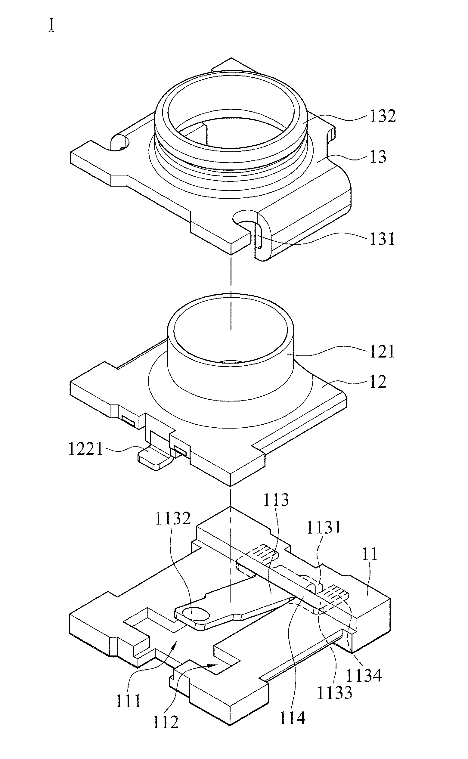
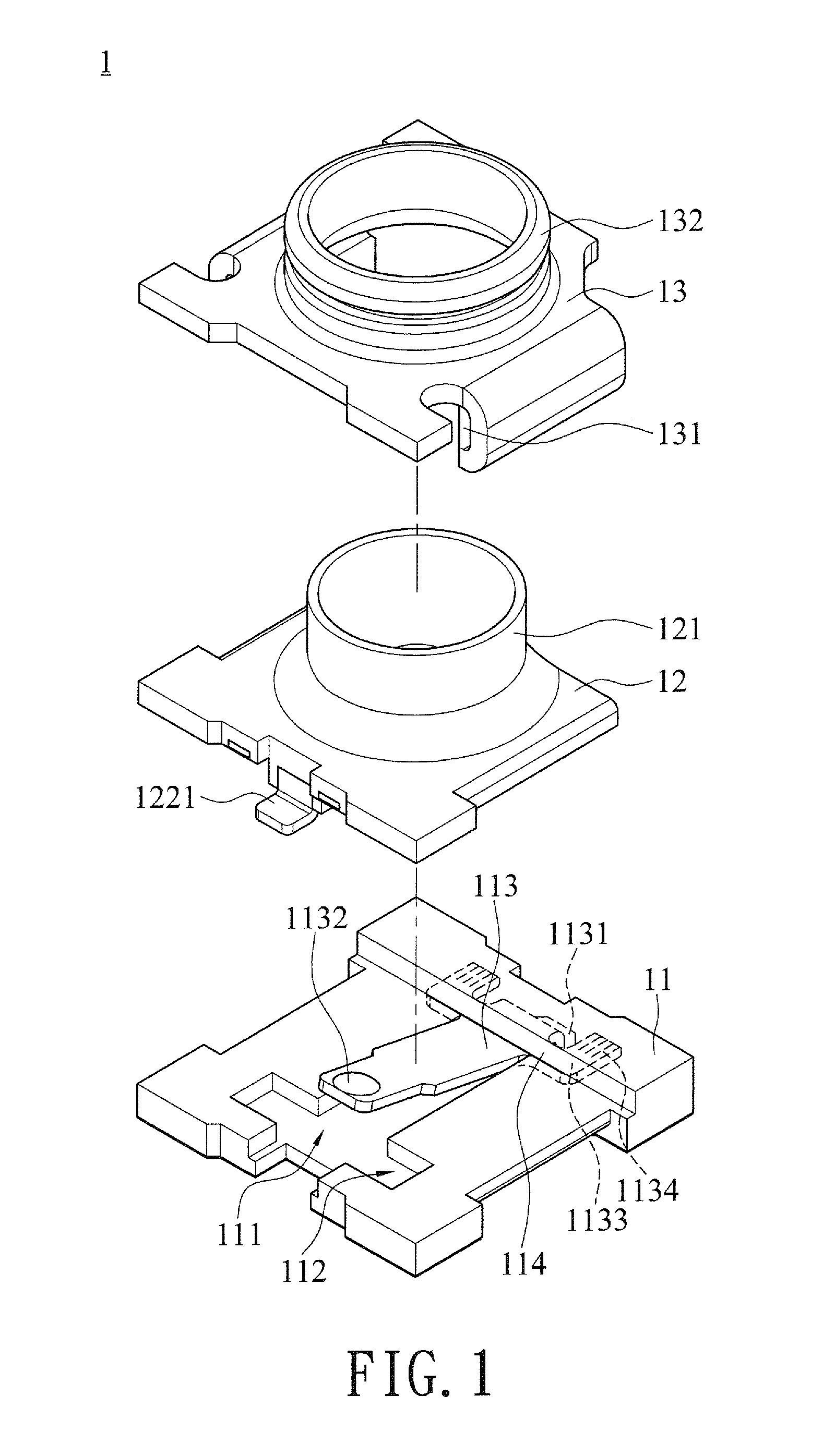
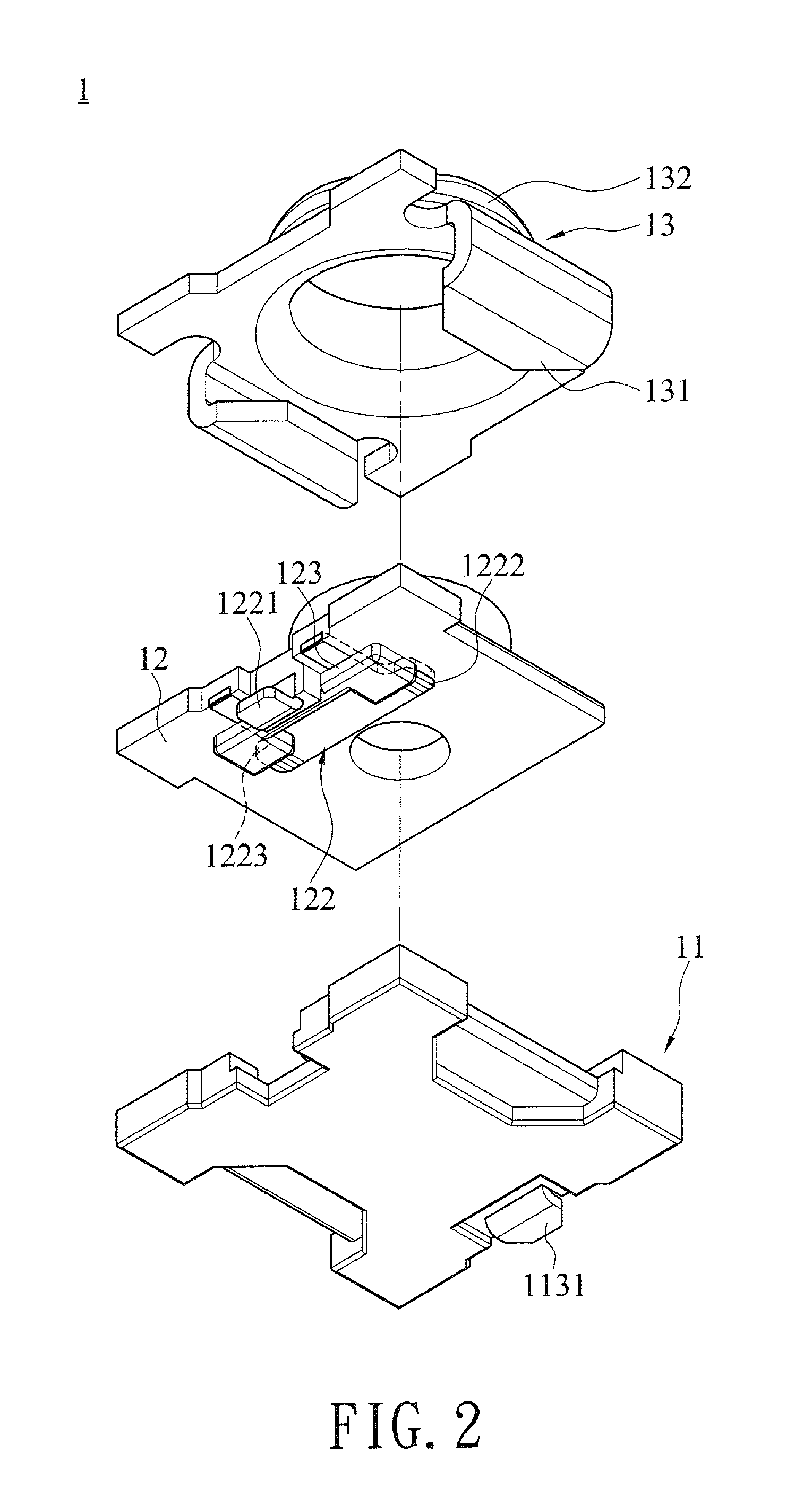
[0019]With reference to FIGS. 1 to 3 for exploded views and a cross-sectional view of a three-plate coaxial connector in accordance with a preferred embodiment of the present invention respectively, the three-plate coaxial connector 1 comprises a base 11, a cover 12 and a metal casing 13.

[0020]The base 11 is a rectangular plate made of an electrically insulating material by insert molding process, and a receiving slot 111 is formed at the center of the base 11 and a positioning groove 112 is formed on a side of the receiving slot 111, and a first electrically conductive plate 113 is buried into the other side of the receiving slot 111 by a molding method, and a positioning surface 114 is formed thereon, so that the positioning surface 114 and the...


PUM


Abstract

A three-plate coaxial connector includes a base, a cover and a metal casing. The base includes a first electrically conductive plate buried in the base by a molding method, and the casing also includes a second electrically conductive plate buried in the casing by the molding method. The modular design of the three-plate coaxial connection reduces the level of difficulty and improves the convenience and efficiency in an assembling process. The first electrically conductive plate and the second electrically conductive plate have at least one first flap and at least one second flap respectively for improving the stability of a molding process. In addition, various positioning structures are designed at the base and the cover to enhance the positioning effect for the engagement while improving the accuracy and stability of the assembling process.

Description

CROSS-REFERENCE TO RELATED APPLICATIONS[0001]This non-provisional application claims priority under 35 U.S.C. §119(a) on Patent Application No(s). 103201524 filed in Taiwan, R.O.C. on Jan. 24, 2014, the entire contents of which are hereby incorporated by reference.BACKGROUND OF THE INVENTION[0002]1. Field of the Invention[0003]The present invention relates to the field of connectors, and more particularly to a three-plate coaxial connector.[0004]2. Description of the Related Art[0005]In general, a coaxial connector is used extensively in electronic devices such as mobile communication devices, global positioning devices and notebook computers for connecting an antenna for transmitting high frequency signals. The coaxial connector comprises an accommodating hole formed in an insulating casing (or a plastic base) for connecting a center conductor protruded from the center of a coaxial plug, an external conductor (which is generally a metal casing) covered onto the exterior of the insu...

Claims


Application Information

Patent Timeline
Patent Type & Authority Applications(United States)
IPC IPC(8): H01R24/38
CPCH01R24/38H01R13/405H01R24/50H01R43/24
Inventor CHEN, CHIU-SHENG
Owner YUE SHENG EXACT INDAL
Why Eureka
Try Eureka