Hard-Mounted EM Telemetry System for MWD Tool in Bottom Hole Assembly

a telemetry system and tool technology, applied in the field of em telemetry system 40, can solve the problem that components may not be retrievable via wirelin

Inactive Publication Date: 2015-08-06
WEATHERFORD TECH HLDG LLC
View PDF10 Cites 17 Cited by
  • Summary
  • Abstract
  • Description
  • Claims
  • Application Information

AI Technical Summary

Problems solved by technology

In other implementations, these components may not be retrievable via wireline or the like.

Method used


Image

  • Hard-Mounted EM Telemetry System for MWD Tool in Bottom Hole Assembly
  • Hard-Mounted EM Telemetry System for MWD Tool in Bottom Hole Assembly
  • Hard-Mounted EM Telemetry System for MWD Tool in Bottom Hole Assembly

Examples


Embodiment Construction

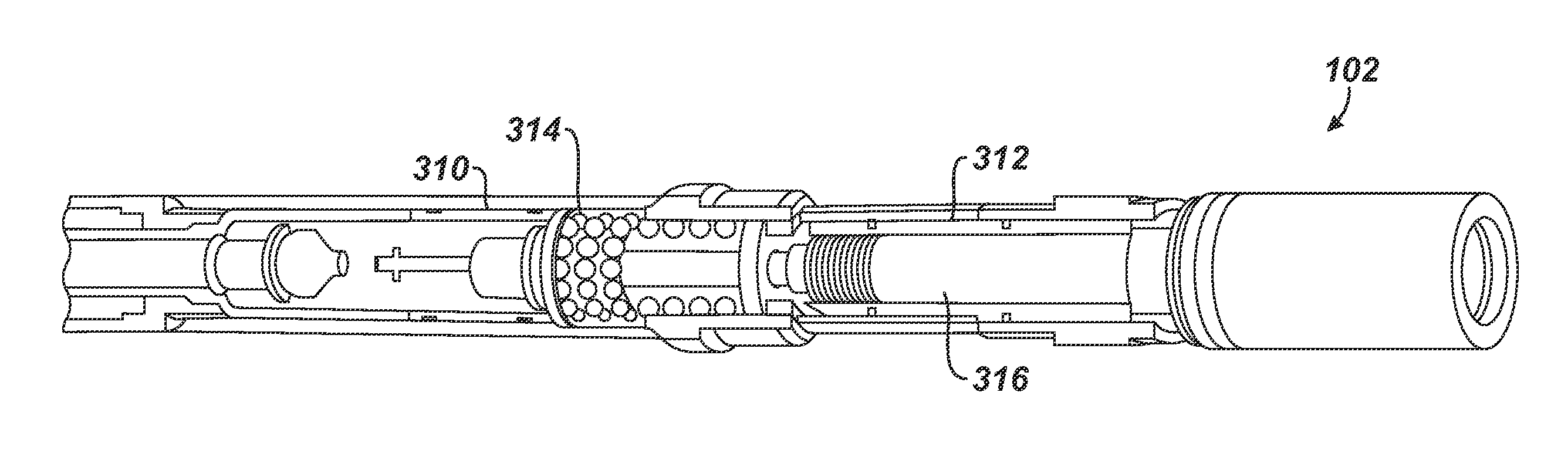
[0041]FIG. 4A illustrates a drilling assembly 100 according to the present disclosure having an air hammer bit 101, a drilling motor 102, an electromagnetic (EM) MWD assembly 104, and a jet sub 108. FIG. 4B schematically illustrates the drilling assembly 100 of FIG. 4A showing an MWD tool 150 and a hard-mounted antenna 170 incorporated into the EM MWD assembly 104.

[0042]The air hammer 101 couples to the drilling motor 102 that is adapted for air drilling, and the drilling motor 102 couples with a shock sub 103 to the MWD assembly 104. A non-magnetic pony collar (not shown) may be used to connect the MWD assembly 104 to the shock sub 103. The MWD assembly 104 includes a mule shoe sub 110, such as a universal bottom hole orientation (UBHO) sub for supporting the MWD tool 150. A double pin connector 105 connects a tool carrier 120 to the UBHO sub 110, and an emitter sub 130 is coupled to the tool carrier 120. As best shown in FIG. 4B, the MWD tool 150 is supported in the tool carrier 1...


PUM


Abstract

An MWD apparatus has a bottomhole assembly for supporting a tool string and an antenna. The tool string has a sensor and an electromagnetic telemetry device. The tool string affixes in a muleshoe and carrier sub of the assembly using a stinger and fastener. An antenna disposes in an emitter sub of the assembly. The antenna is attached to extend from the tool string so the antenna is in electrical communication with the telemetry device. Finally, the portions of the assembly are connected together, and the antenna is affixed in the uphole portion of the assembly using a conductive landing and one or more fasteners. In this way, the tool string and the antenna are held in tension inside the assembly. The MWD apparatus can be used with an air drilling assembly having an air hammer and a motor coupled downhole of the apparatus. Non-magnetic and regular drill collars can couple uphole of the apparatus, along with a jet sub.

Description

BACKGROUND OF THE DISCLOSURE[0001]FIG. 1 illustrates an electromagnetic (EM) telemetry system 40 for a Measurement-While-Drilling (MWD) tool 50 used with a drilling system 20. The MWD tool 50 is deployed in a bottom hole assembly 30 on a drill string 24 from a rig 22 at the surface. The MWD tool 50 obtains various measurements as the bottom hole assembly 30 advances a borehole 12 in the subsurface formation 10. To communicate with the MWD tool 50 during drilling, the EM telemetry system 40 uses a surface antenna 42 and a transceiver 44 to inject and detect current in bi-directional communications with an emitting antenna 60 of a downhole transceiver 45 of the MWD tool 50.[0002]The EM telemetry system 40 can be similar to Weatherford's EMpulse electromagnetic (EM) measurement-while-drilling (MWD) system. Overall, the EM telemetry system 40 allows operators to drill and survey the borehole 12 independent of the rig hydraulics. For example, by using EM telemetry rather than mud pulse t...

Claims


Application Information

Patent Timeline
Patent Type & Authority Applications(United States)
IPC IPC(8): E21B49/00E21B47/06
CPCE21B47/06E21B49/003E21B21/16E21B47/01E21B4/02E21B47/13
Inventor WEISBECK, DENISO'CONNOR, RYANTRAPASSO, GIUSEPPEMACMILLAN, CLAYTON W.RODRIGUEZ, ALIARCID F.CRNOGORAC, RAJKO F.PULFER, TROYMALAGARIE, STEVEN P.KUNTZ, JONATHAN F.KUHLMAN, MICHAEL W.FLORES, RUDY C.LUDINSKY, MICHAEL V.
Owner WEATHERFORD TECH HLDG LLC
Why Eureka
Try Eureka