Pressure-increasing unit

a technology of pressure-increasing units and gas pressure, which is applied in the direction of hot gas positive displacement engine plants, gas/liquid distribution and storage, packaging, etc., can solve the problems of relative high cost and further increase, and achieve the effect of reducing gas pressure costs, increasing local pressure, and being easy to install

Active Publication Date: 2015-08-06
BF ENERGIA OY
View PDF6 Cites 0 Cited by
  • Summary
  • Abstract
  • Description
  • Claims
  • Application Information

AI Technical Summary

Benefits of technology

[0006]The invention provides considerable advantages. Thus the device, which also as auxiliary equipment is readily installable in a system using pressurized gas, such as pressurized air, may be used separately from the actual pressurization main unit in order to increase the pressure of the gas locally. This enables the laborious and resource-demanding purification and drying required by continuous new gas to be pressurized to be avoided. The device thus enables gas pressurization costs to be reduced significantly.
[0007]By using the arrangement according to the invention to be provided in connection with the object of use or in the vicinity thereof, solutions can be avoided wherein pressurized gas to be possibly recovered is conveyed, by using parallel and expensive pipelines, to the primary compressor of the system for re-pressurization.
[0008]When made sufficiently compact, the arrangement is easy to take directly to the object of use and connect it therein to the pressure line of gas-utilizing applications.

Problems solved by technology

Moisture removal, for instance, causes relatively high costs, which are further increased by the fact that in an ordinary system the pressurized gas is allowed to be discharged into the space surrounding the object of use.

Method used


Image

  • Pressure-increasing unit
  • Pressure-increasing unit
  • Pressure-increasing unit

Examples


Embodiment Construction

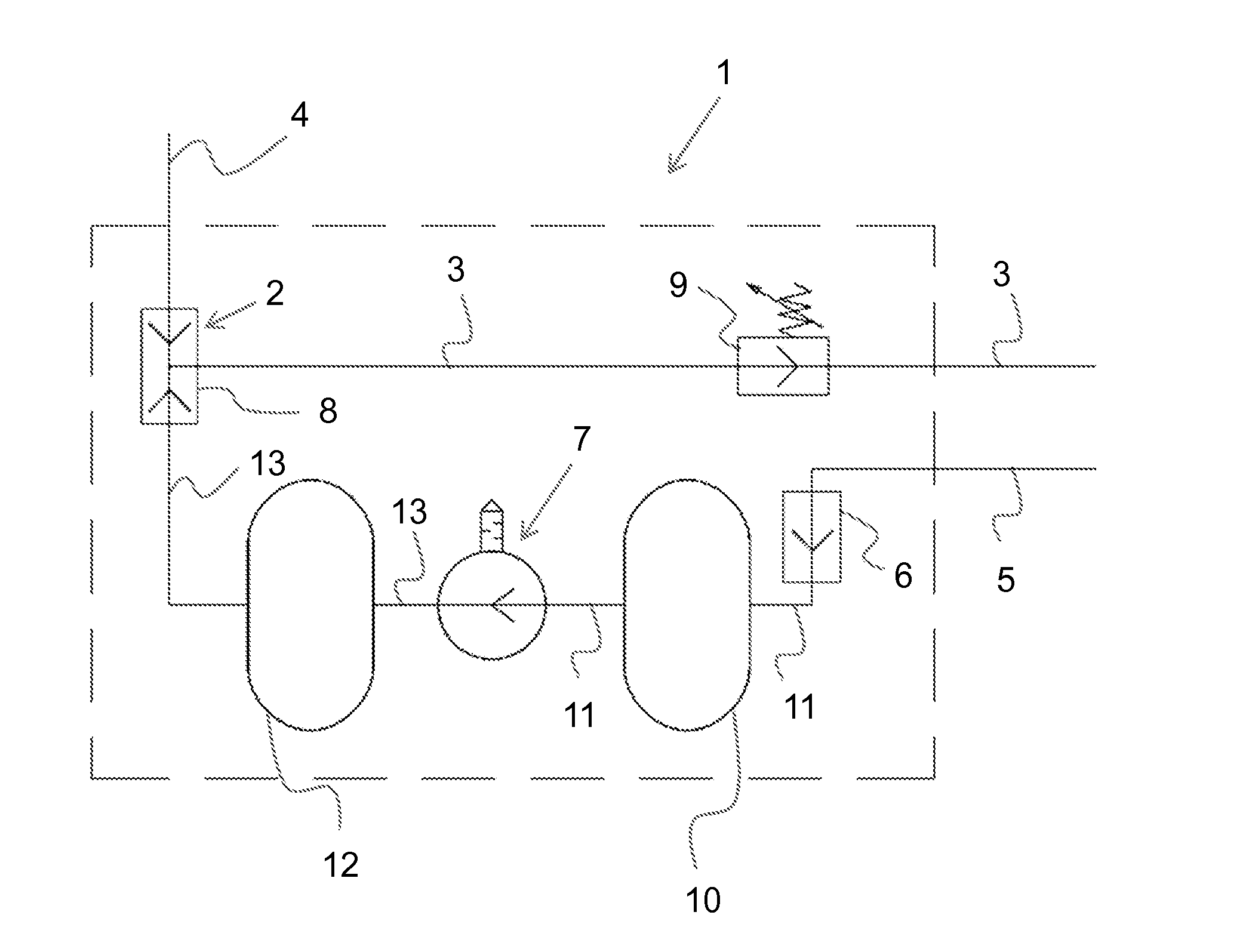
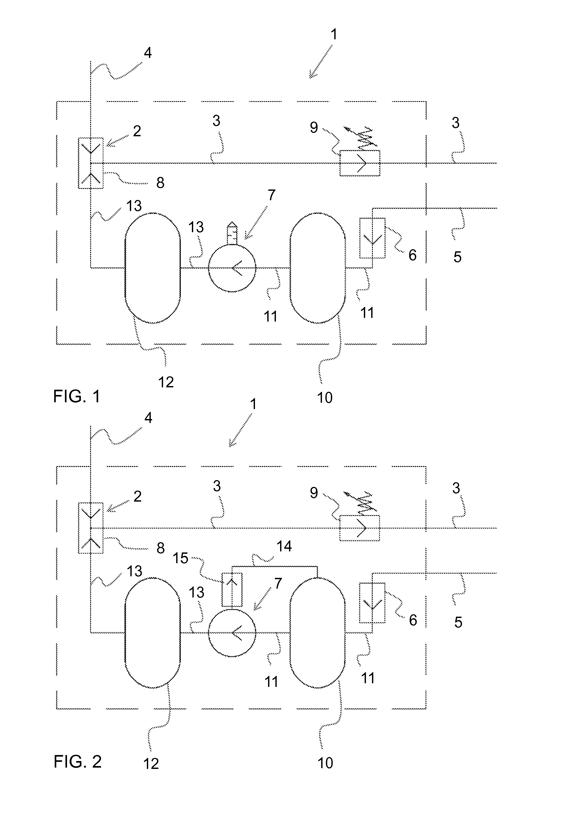
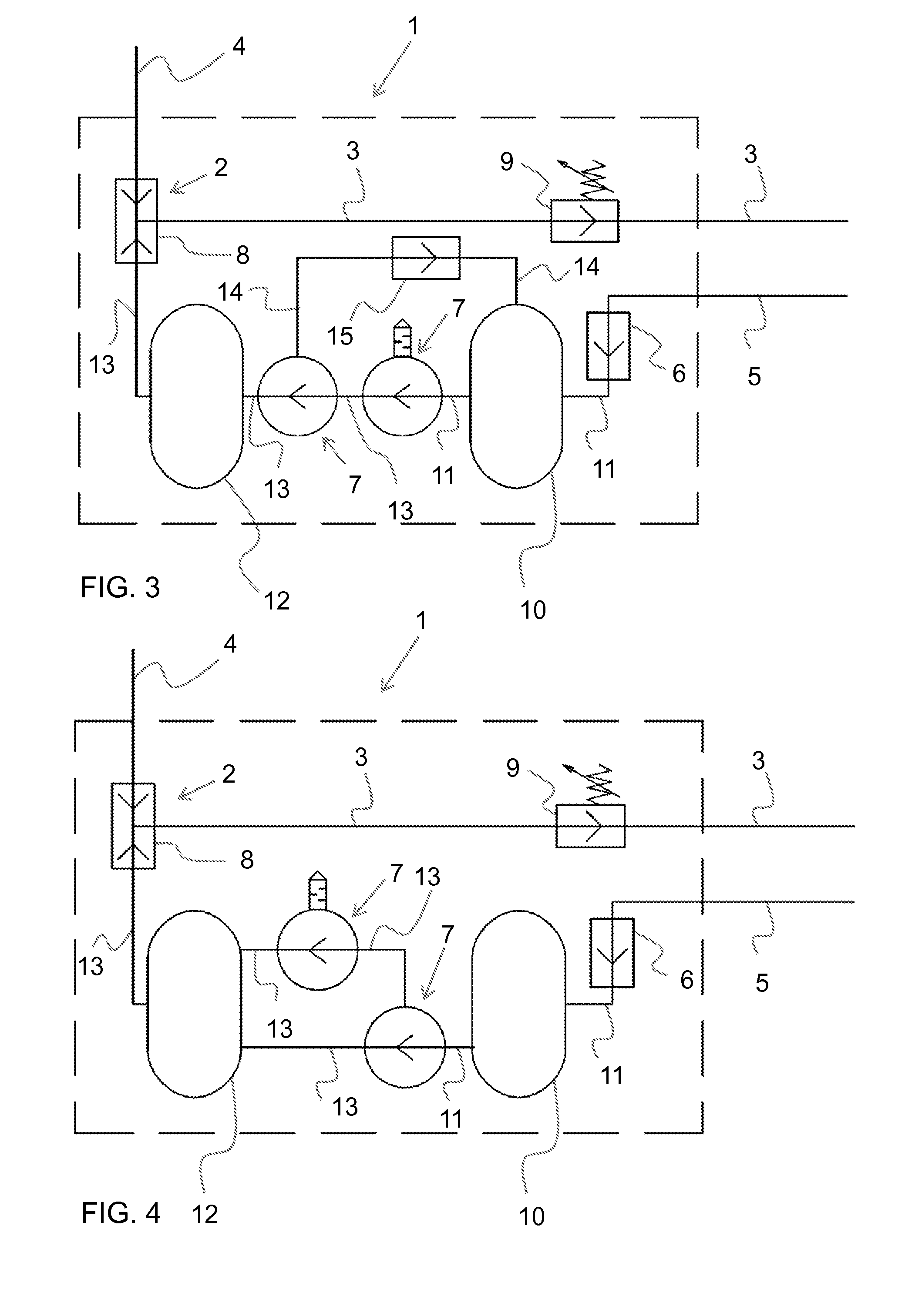
[0015]The present figures do not show the pressure-increasing unit in scale but the figures are schematic, illustrating the structure and operation of the preferred embodiment in principle. The most essential structural parts of the solution indicated by reference numerals in the attached figures then correspond to the structural parts marked with reference numerals in this specification.

[0016]A pressure-increasing unit 1 according to FIGS. 1 to 4 most preferably comprises first receiving means 2 arranged to receive and guide pressurized gas further to at least one first pipeline 3 through which the pressurized gas is conveyed to applications utilizing it; no such applications are separately shown in this connection. Typically, the pressurized gas is conveyed to the pressure-increasing unit along a pipeline 4 from a main source, such as one or more compressors, known per se and omitted from this description.

[0017]Reduced-pressure gas that passes through devices using pressurized gas...


PUM


Abstract

The present invention relates to a pressure-increasing unit (1) comprising first receiving means (2) for receiving a pipeline (4) conveying pressurized gas, at least one first pipeline (3) for further transferring the pressurized gas to applications utilizing it, and second receiving means (6) for receiving a second pipeline (5) conveying reduced-pressure gas returning from the applications. The present solution is characterized in that the receiving means (6) are connected with at least one pressure intensifier (7). This pressure intensifier, in turn, is connected to the first receiving means (2) receiving pressurized gas for transferring gas re-pressurized by a substitution means (8) back to the applications utilizing it.

Description

BACKGROUND OF THE INVENTION[0001]The present invention relates to a pressure-increasing unit as claimed in the preamble of claim 1. Such a device is utilized in a pressurized gas system in particular, such a system comprising at least one compressor. The system further includes a suction pipe connected to the compressor for gas input, and an output pipe for gas pressurized by the compressor. The output pipe is connected to a distribution pipeline through which gas is distributed to objects of use, such as blow couplings and actuator couplings, provided in an operating space.[0002]In previously known systems, the gas used therein always has to be dried and otherwise purified prior to allowing the gas to enter the distribution pipeline in order to enable possible malfunctions in the objects of use to be avoided. Moisture removal, for instance, causes relatively high costs, which are further increased by the fact that in an ordinary system the pressurized gas is allowed to be discharge...

Claims


Application Information

Patent Timeline
Patent Type & Authority Applications(United States)
IPC IPC(8): F04D13/16
CPCF02G1/00F04D13/16F17D1/04F04B41/00Y10T137/3127
Inventor KORPELA, SAMULI
Owner BF ENERGIA OY
Why Eureka
Try Eureka