
Method for determining the distribution of an imaging agent

a technology of imaging agent and distribution method, which is applied in the field of imaging agent distribution measurement, can solve the problems of inhomogeneous uptake, slow uptake, and inability to accurately represent the uptake, so as to improve the accuracy of the method, improve the accuracy, and reduce the complexity of the imaging system

Active Publication Date: 2015-08-06
KONINKLJIJKE PHILIPS NV
View PDF4 Cites 1 Cited by
  • Summary
  • Abstract
  • Description
  • Claims
  • Application Information

AI Technical Summary

Benefits of technology

The invention provides an improved method for accurately determining the activity of an imaging agent (such as a radiotracer) within an imaging system. By assigning additional imaging agent distribution basis functions to compartments within the body, the method can better approximate the actual activity distribution during uptake. The representation of the three-dimensional imaging agent activity in each compartment by the product of a scaling factor and a non-affine transformation of a template imaging agent activity can provide a better fit with a measured planar image of the imaging agent activity, resulting in improved accuracy and reduced processing time. The method can also help improving the accuracy of calculating the necessary dose of a therapy agent and reducing processing time.

Problems solved by technology

At other positions within particular organs the uptake has been found to be particularly slow.
Thus the assumptions of a homogeneous imaging agent compartment distribution made in previous approaches to model the imaging agent distribution such as such as QPLANAR and EQPLANAR restrict the accuracy of these approaches.
Likewise, imaging agent distribution basis functions as determined from a three-dimensional functional image and held constant for all scintigraphies may inadequately represent the inhomogeneous uptake.

Method used


Image

  • Method for determining the distribution of an imaging agent
  • Method for determining the distribution of an imaging agent
  • Method for determining the distribution of an imaging agent

Examples


first embodiment

[0038]In the invention the imaging agent activity in a compartment is represented by a single non-affine transformation of the template imaging agent activity as determined from a functional image of the volume. Thus taking for example Equation 2 above, the activity resulting from the imaging agent distribution basis function in the first compartment (n=1) can be represented by the matrix:

B1,1(x,y,z)=k1,1·(C(x,y,z)*S1(x,y,z))2  Equation 4

for the exemplary case where the non-affine activity transformation of a square power law is used and k1,1 is a scaling factor associated with compartment 1 and the imaging agent distribution basis function 1.

second embodiment

[0039]In the invention the imaging agent activity in a compartment is represented by the combination of a non-affine transformation and an affine transformation of the template imaging agent activity as determined from a functional image of the volume. Thus taking for example Equation 2 above, the activity resulting from the imaging agent distribution in the first compartment (n=1) may be represented by the matrix:

T1=k1,1·(C(x,y,z)*S1(x,y,z))2+k1,2·(C(x,y,z)*S1(x,y,z))+k1,3*S1(x,y,z)  Equation 5

for the exemplary case where the non-affine activity transformation of a square power law is used and wherein k1,1, k1,2, k1,3 are scaling factors associated with compartment 1. The scaling factors in either embodiment may be adjusted independently in order to improve the correspondence between the calculated projected imaging agent activity and the intensity of the acquired planar image or scintigraphy. This second embodiment is well suited to fitting to the planar image when a locally high ...


PUM


Abstract

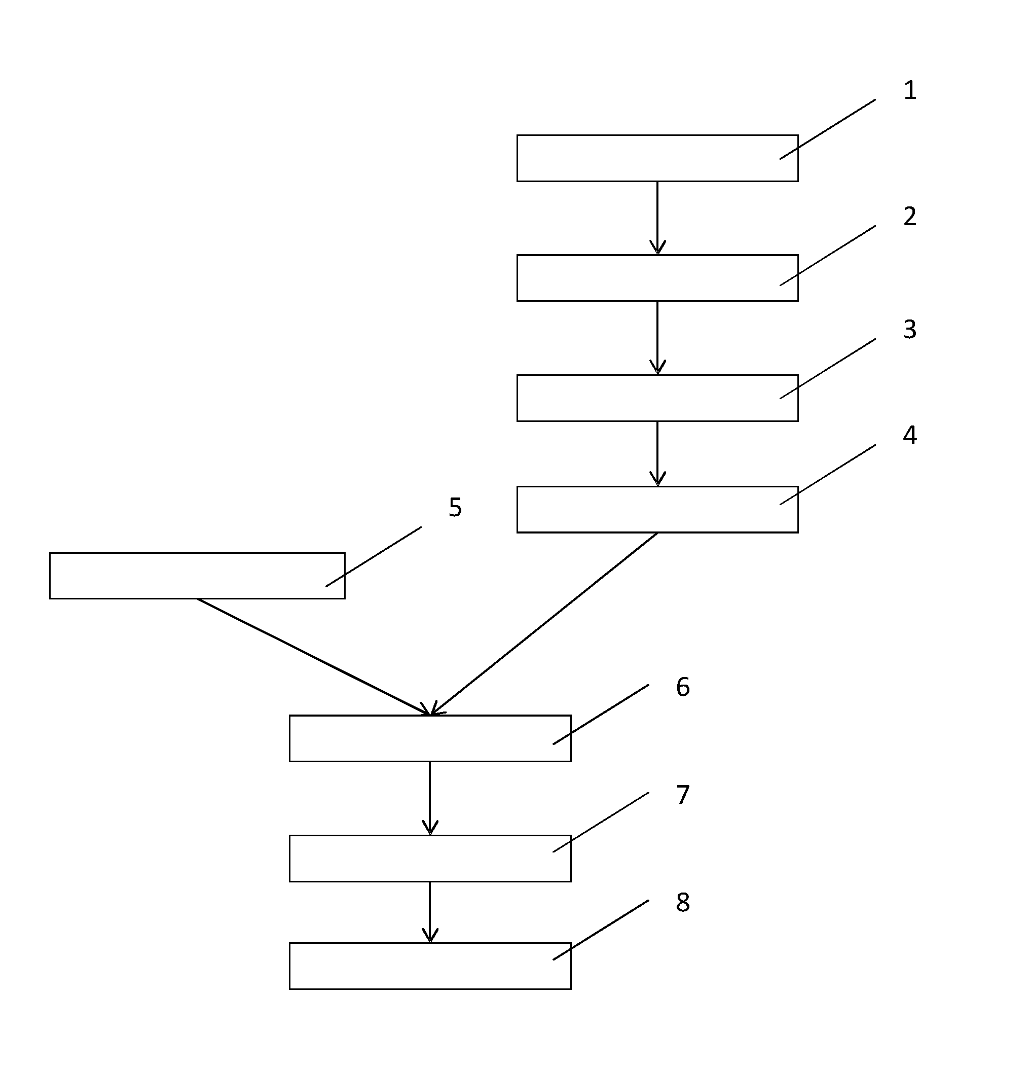
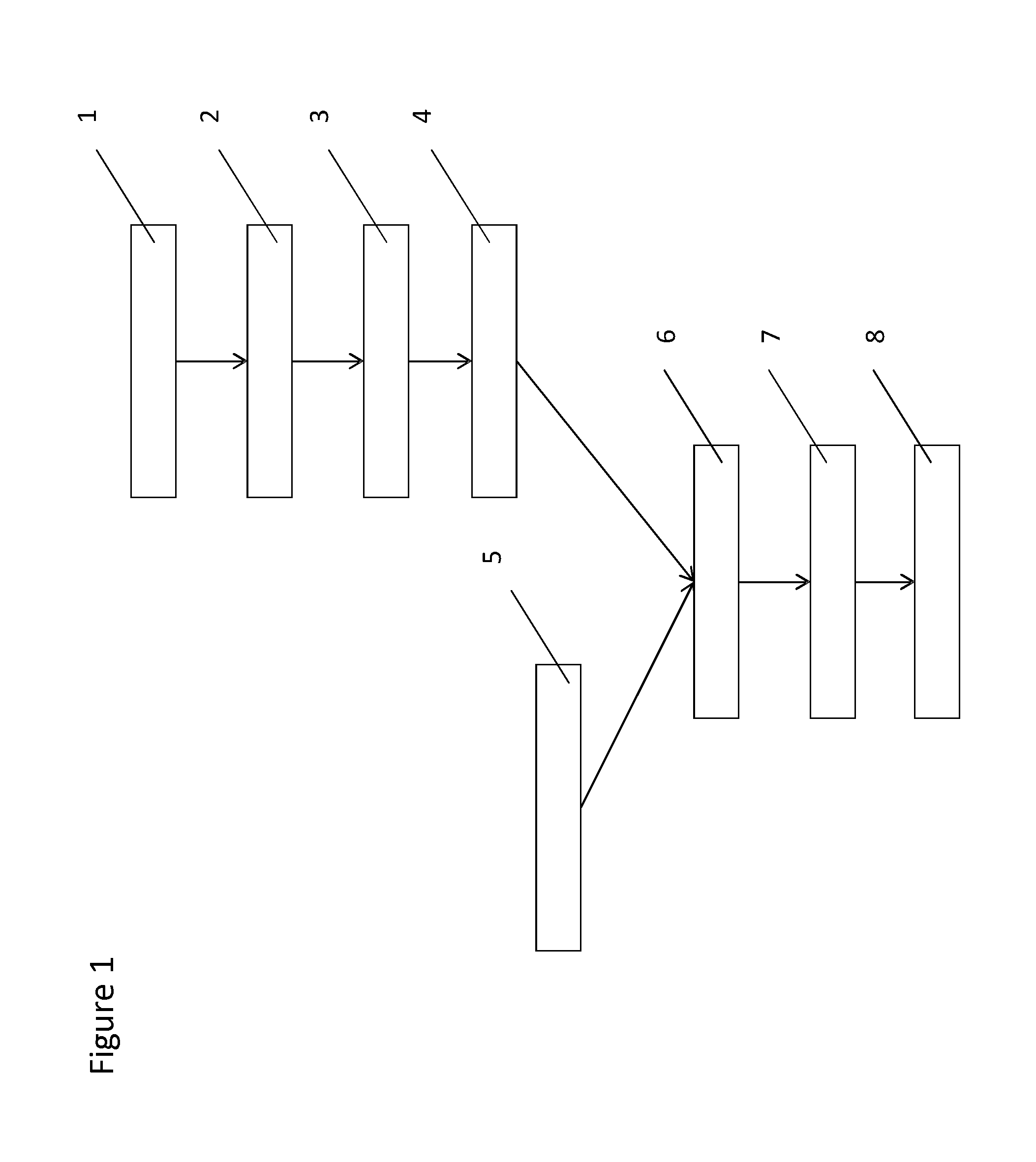
The present invention relates to a method for determining the distribution of an imaging agent in a volume. The method comprises the acquisition of at least one three-dimensional functional image of the volume; the segmentation of the volume into one or more compartments; the representation of the three-dimensional imaging agent activity from the functional image by the product of a scaling factor and a non-affine transformation of a template imaging agent activity; the calculation of a projected imaging agent activity from the thus represented imaging agent activity on a planar surface; the acquisition of a planar image of the imaging agent activity in the volume; the registration of the projected imaging agent activity with the planar image; the comparison of the acquired planar image with the calculated projected imaging agent activity; and the modification of the representation of the three-dimensional imaging agent activity.

Description

FIELD OF THE INVENTION[0001]The invention relates to a method for analysing images from medical imaging systems. More specifically the invention finds application in the field of imaging agent distribution measurement, and even more specifically the invention can be applied to measure the distribution of a radiotracer in the field of dose optimization in the delivery of targeted radiotherapy.BACKGROUND OF THE INVENTION[0002]In the field of medical imaging the measurement of radiotracer distributions within a body is used to indicate the functioning of various biological processes. The body may be for example a human or animal or other organism, and the radiotracer may be a chemical compound that is preferentially uptaken by particular organs in the body. In order to measure the spatial distribution of the radiotracer, tomographic imaging such as PET and SPECT is typically used, resulting in high accuracy three-dimensional images of the radiotracer. The images may further be segmente...

Claims


Application Information

Patent Timeline
IPC IPC(8): G06T7/00H04N13/02G06T3/00G06K9/62
CPCG06T7/0016G06T2207/10104G06T2207/10108G06T2207/10128H04N13/0203G06K9/6215G06T3/00G06T7/0012G06T7/0081G06T2207/30004H04N13/204G06F18/22
Inventor BERKER, YANNICK
Owner KONINKLJIJKE PHILIPS NV
Learn More