Insertion system, insertion supporting device, insertion supporting method and recording medium

a technology of insertion system and supporting device, which is applied in the field of insertion system, insertion supporting device, insertion supporting method and recording medium, can solve the problems of not easily judged whether or not all required regions are required, and suggested a method of detection and display, so as to prevent oversight of observation or operation regions, easy to judge, and quick

Inactive Publication Date: 2015-08-13
OLYMPUS CORP
View PDF4 Cites 14 Cited by
  • Summary
  • Abstract
  • Description
  • Claims
  • Application Information

AI Technical Summary

Benefits of technology

[0015]According to the present invention, there can be provided an insertion system, an insertion supporting device, an insertion supporting method and a program that can supply information to judge which position of an insertion subject is being acquired image or operated and therefore enables an operator to easily judge which region of the insertion subject is being acquired image or operated and whether all required regions could be acquired images or operated, so that it is possible to prevent oversight of observation or operation regions.
[0016]Additionally, according to the present invention, when a positional relation of an inserting section to an insertion subject which is calculated by a positional relation calculating section is output by an output section, a control section sets at least a start point of the output, and in this case, the positional relation is not always output but is output only when necessary, so that useless information is not supplied but the output can be easy to understand (easy to see, hard to be mistaken, or can quickly be judged).

Problems solved by technology

In general, there are only a few regions that become marks in an insertion subject, and hence when it is not easily judged only from an acquired image which region of the insertion subject is being observed, it is also not easily judged whether or not all required regions could be imaged (observed).
However, there has not been suggested a method of detecting and displaying which region of the insertion subject is being imaged (observed).

Method used


Image

  • Insertion system, insertion supporting device, insertion supporting method and recording medium
  • Insertion system, insertion supporting device, insertion supporting method and recording medium
  • Insertion system, insertion supporting device, insertion supporting method and recording medium

Examples


first embodiment

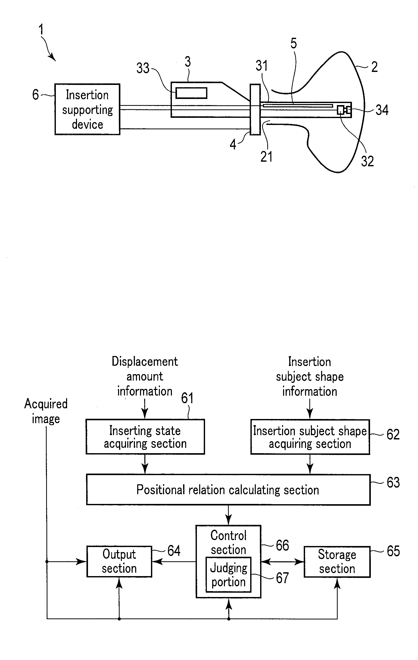
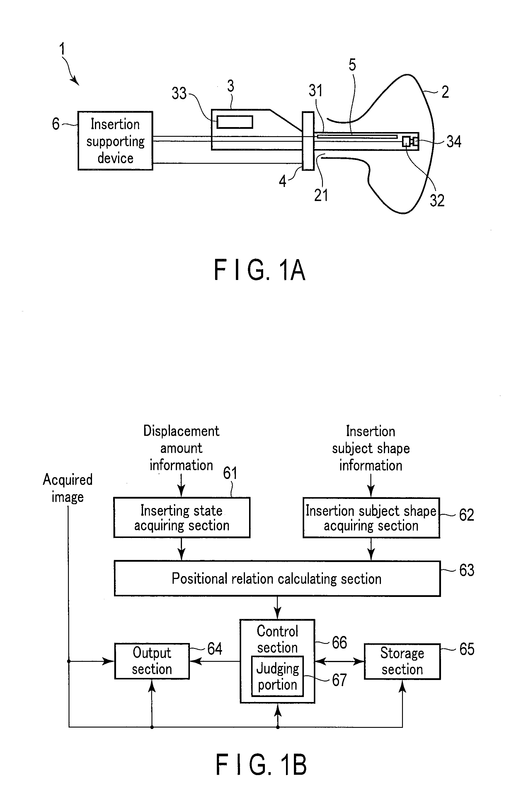
[0057]As shown in FIG. 1A, an insertion system 1 according to a first embodiment of the present invention is constituted of an inserting tool 3 including an inserting section 31 to be inserted into an insertion subject 2 and an image acquisition section 32 that acquires image of the insertion subject 2, an insertion and rotation detecting section 4 and a fiber shape sensor 5 as detecting sections that detect displacement amount information of the inserting section 31, and an insertion supporting device 6 concerned with the first embodiment of the present invention which acquires inserting state information of the inserting section 31 from the displacement amount information from the insertion and rotation detecting section 4 and the fiber shape sensor 5, and calculates a positional relation of the inserting section 31 in relation to the insertion subject 2 on the basis of the inserting state information and shape information of the insertion subject 2 to display and output the calcu...

second embodiment

[0135]Next, a second embodiment of the present invention will be described.

[0136]In the insertion system 1 concerned with the above first embodiment, a display section that displays an acquired image is constituted as the same device as the output section 64, but as shown in FIG. 16A, an insertion system 1 concerned with the present second embodiment further includes, as the display section, a display device 9 that is a device separate from the output section 64. In such a constitution, as shown in FIG. 16B, an inserting state display 642 is only carried out in the output section 64, and an acquired image display 641 is only carried out in the display device 9.

[0137]Therefore, when the output section 64 is disposed in the vicinity of the display device 9, a calculation result of a positional relation calculating section 63 and an image acquired by an image acquisition section 32 can substantially simultaneously be seen, and both of the result and the image can simultaneously be reco...

third embodiment

[0138]Next, a third embodiment of the present invention will be described.

[0139]An insertion system 1 concerned with the present third embodiment is an example of a case where an inserting tool 3 is such a hard endoscope device as shown in FIG. 17. In this hard endoscope device, differently from the soft endoscope device in the above first embodiment (and the second embodiment), an inserting section 31 does not have flexibility, and hence a shape thereof is constant.

[0140]Therefore, it is not necessary to arrange coils in a longitudinal direction of a fiber shape sensor 5 or the inserting section 31, and it is also not necessary for a positional relation calculating section 63 to calculate shape information of the inserting section 31. The shape information of the inserting section 31 may only be stored or input in the positional relation calculating section 63 beforehand.

[0141]The other respects are similar to those of the insertion system concerned with the above first embodiment ...


PUM


Abstract

An inserting state acquiring section is configured to acquire inserting state information of an inserting section that is to be inserted into an insertion subject, an insertion subject shape acquiring section is configured to acquire insertion subject shape information that is shape information of the insertion subject, and a positional relation calculating section is configured to be input the inserting state information and the insertion subject shape information and to calculate a positional relation of the inserting section to the insertion subject. When an output section outputs the calculation result of the positional relation calculating section, a control section is configured to control an output state of the calculation result in the output section.

Description

CROSS-REFERENCE TO RELATED APPLICATIONS[0001]This application is a Continuation application of PCT Application No. PCT / JP2013 / 078738, filed Oct. 23, 2013 and based upon and claiming the benefit of priority from the prior Japanese Patent Application No. 2012-235634, filed Oct. 25, 2012, the entire contents of which are incorporated herein by reference.BACKGROUND OF THE INVENTION[0002]1. Field of the Invention[0003]The present invention relates to an insertion system in which an inserting section of an inserting tool such as an endoscope or a catheter is inserted into an insertion subject to perform an observation or an operation, an insertion supporting device which supports the insertion of the inserting section into the insertion subject in such an insertion system, an insertion supporting method, and a recording medium non-transitory storing a program which allows a computer to execute a procedure of the insertion supporting device.[0004]2. Description of the Related Art[0005]As a...

Claims


Application Information

Patent Timeline
Patent Type & Authority Applications(United States)
IPC IPC(8): A61B1/00A61B1/05
CPCA61B1/00059A61B1/05A61B1/00004A61B1/00036A61B1/0005A61B5/065A61B5/1076G02B23/2423G02B23/26A61B1/00009A61B5/061F04C2270/0421A61B1/009
Inventor FUJITA, HIROMASATOJO, RYO
Owner OLYMPUS CORP
Why Eureka
Try Eureka