Therapeutic wrap with pattern zone

a pattern zone and wrap technology, applied in the field of therapeutic wraps with pattern zones, can solve the problems of kinking, affecting the effect of treatment effect,

Active Publication Date: 2015-08-13
WILFORD MICHAEL L +1
View PDF5 Cites 10 Cited by
  • Summary
  • Abstract
  • Description
  • Claims
  • Application Information

AI Technical Summary

Benefits of technology

[0008]The present invention relates to therapy wraps having a plurality of diffing seal pattern zones. The wraps may be constructed of two or more layers of material which are sealed together to from a fluid tight cavity bounded by a cavity seal. Additionally, at least one hose is provided such that one e

Problems solved by technology

Kinking may also occur due to the weight of the patient's own body resting on the fluid wrap, for example, in the case of an ankle wrap the weight of a raised leg may place pressure on an ankle and thereby block fluid flow through the wrap.
However, t

Method used


Image

  • Therapeutic wrap with pattern zone
  • Therapeutic wrap with pattern zone
  • Therapeutic wrap with pattern zone

Examples


Embodiment Construction

[0018]Throughout the specification, wherever practicable, like structures will be identified by like reference numbers.

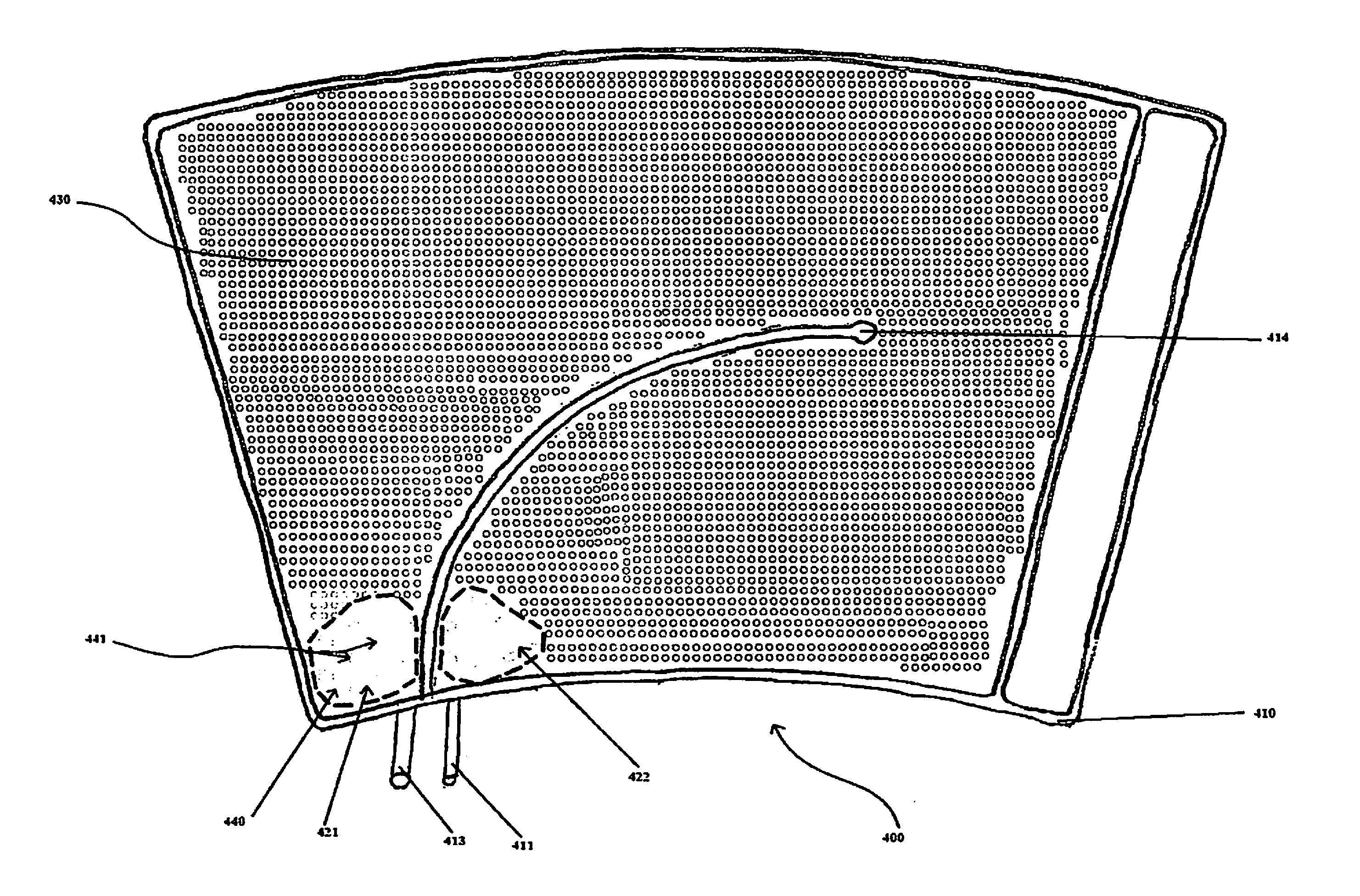
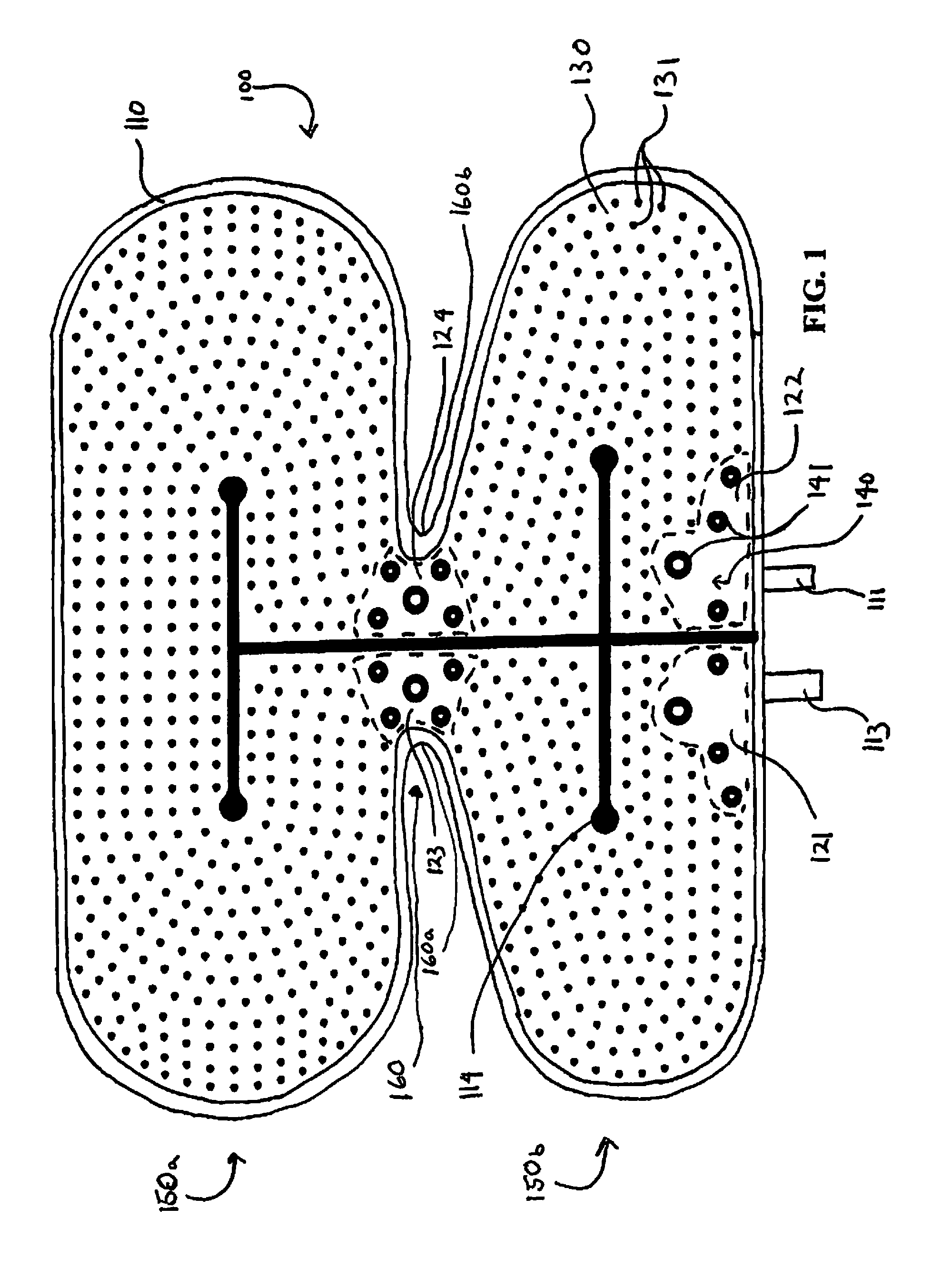
[0019]It is preferable that the therapy system of the present invention is used to apply thermal and / or compression therapy utilizing various specially designed wraps. The particular shape and benefits afforded by the various specially designed wraps for use with the therapy system will be described in detail below. The wraps may be constructed for the application of thermal treatment using a circulated heated or cooled fluid, the application of compression therapy, or both. Thermal therapy only wraps may be constructed utilizing at least two layers of material and at least two hoses. The two or more layers of material and two or more hoses are laminated together at least about the perimeter of the two layers of material thereby forming a cavity between at least two or more layers and such that the two hoses provide pathways for the ingress and egress of fluid to an...


PUM


Abstract

The subject matter of the invention relates to therapy wraps for the application of compression and/or thermal therapy to a patient. The wraps are formed of at least two layers of material which are sealed together to form at least one cavity between them. At least two layers of the wrap are sealed together using a plurality of different seal patterns. A first seal pattern is provided in at least one zone. The zone is surrounded by a perimeter seal, an internal seal or at least one different seal pattern or a combination thereof. The pattern within the zone or zones provides higher volume fluid flow paths than the pattern or patterns surrounding the zone or zones.

Description

CROSS-REFERENCE TO RELATED APPLICATION[0001]Not ApplicableFEDERALLY SPONSORED RESEARCH OR DEVELOPMENT[0002]Not Applicable.BACKGROUND OF THE INVENTION[0003]The present invention relates generally to thermal and compression systems used in the application of thermal and compression therapy to a patient's body. In practice, the wraps are connected to a thermal and compression machine that may supply compressed gas and a thermal fluid to the wrap. Generally, compressed gas may be pumped through a tube to the wrap while a thermal transfer fluid may be circulated through the wrap and machine by pumping fluid, that has been heated or cooled by the machine, from a reservoir in the machine through a tube connected to a wrap, circulating the fluid through the wrap, and allowing the fluid to exit the wrap through another tube which returns the fluid to the machine. An example of one such thermal and compression machine is described in U.S. Patent Application Publication 2011 / 0257565 filed on b...

Claims


Application Information

Patent Timeline
IPC IPC(8): A61H9/00
CPCA61H2201/0103A61H9/0078A61F7/02A61F2007/0054A61H9/0092A61H2201/0207A61H2201/0214A61H2201/0242
Inventor WILFORD, MICHAEL L.UBIDIA, FERNANDO A.
Owner WILFORD MICHAEL L
Why Eureka
Try Eureka