Eureka AIR delivers breakthrough ideas for toughest innovation challenges, trusted by R&D personnel around the world.

Liquid ejecting head and liquid ejecting apparatus

Active Publication Date: 2015-08-13
SEIKO EPSON CORP
View PDF1 Cites 3 Cited by
  • Summary
  • Abstract
  • Description
  • Claims
  • Application Information

AI Technical Summary

Benefits of technology

This patent is about a new liquid ejecting head and apparatus that can prevent excessive bending of the piezoelectric layer without deforming the vibrating plate. The invention improves the rigidity of the piezoelectric layer and suppresses the movement of the vibrating plate when generating pressure fluctuations. A thicker vibrating plate in certain areas helps prevent excessive bending of the piezoelectric layer and a thinner vibrating plate in certain areas allows for sufficient deformation to generate an appropriate pressure fluctuation. The invention also includes the use of a zirconium oxide layer to prevent lead diffusion and further ensures movement of the vibrating plate on the outside of the piezoelectric layer at least when generating pressure fluctuations. Overall, this patent improves the reliability of the liquid ejecting head and its performance.

Problems solved by technology

However, if the vibrating plate is thick, a portion on which a piezoelectric layer is not stacked in an area corresponding to a pressure chamber has an excessive thickness.
Accordingly, the pressure fluctuation may be insufficiently transferred to liquid in the pressure chamber.

Method used


Image

  • Liquid ejecting head and liquid ejecting apparatus
  • Liquid ejecting head and liquid ejecting apparatus
  • Liquid ejecting head and liquid ejecting apparatus

Examples


Embodiment Construction

[0027]Hereinafter, embodiments for implementing the invention will be described with reference to the accompanying drawings. In the embodiments which will be described below, various limitations may be applied to a specific example to be appropriate for the invention. However, embodiments of the invention are not limited so long as not departing from the scope of the invention in the description which will be made below. In the description which follows, a liquid ejecting apparatus according to embodiments of the invention may include an ink jet printer (hereinafter, a printer) as an example. An ink jet recording head (hereinafter, recording head) which is one type of a liquid ejecting head may be mounted in the ink jet printer.

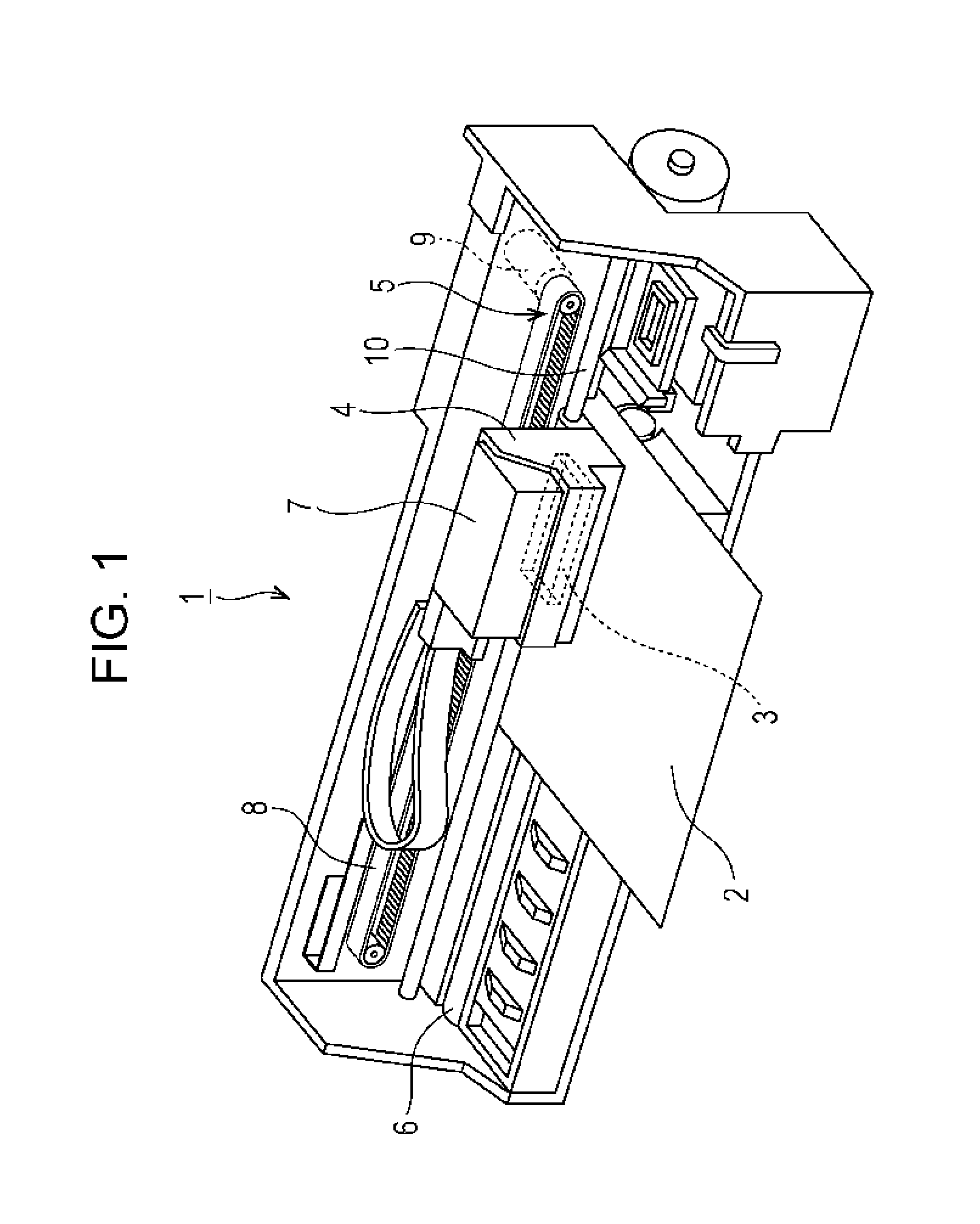
[0028]A configuration of a printer 1 will be described with reference to FIG. 1. The printer 1 is an apparatus which records an image or the like on a surface of a recording medium (one type of impact target) 2 such as a recording paper by ejecting liquid typ...


PUM


Abstract

At an area corresponding to a pressure chamber, the width of a lower electrode film in a nozzle row direction is narrower than the width of the pressure chamber in the same direction. A vibrating plate at the area corresponding to a pressure chamber includes an area P1, an area P2, and an area P3. The area P1 is an area on which the piezoelectric layer to be an activation portion is stacked. The area P2 is an area on which the piezoelectric layer to be an inactivation portion is stacked. The area P3 is an area on which the piezoelectric layer is not stacked. When the thicknesses of the vibrating plate at the areas P1, P2 and P3 are set to, respectively, t1, t2, and t3, the following expression is satisfied:t1>t2≧t3  (1).

Description

CROSS-REFERENCE TO RELATED APPLICATIONS[0001]The present application claims priority to Japanese Patent Application No. 2014-024066 filed on Feb. 12, 2014, which is hereby incorporated by reference in its entirety.BACKGROUND[0002]1. Technical Field[0003]Embodiments of the present invention relate to a liquid ejecting head that ejects liquid by driving a piezoelectric element and to a liquid ejecting apparatus that includes the liquid ejecting head.[0004]2. Related Art[0005]A liquid ejecting apparatus is an apparatus that includes a liquid ejecting head. For example, an ink jet printer and an ink jet plotter are examples of the liquid ejecting apparatus. Various types of liquid can be ejected from the liquid ejecting head.[0006]Recently, the liquid ejecting apparatus has been also applied to or included in various manufacturing apparatuses because of the liquid ejecting apparatus has the advantage of being able to accurately impact or deposit very small amounts of liquid at a predete...

Claims


Application Information

Patent Timeline
IPC IPC(8): B41J2/14
CPCB41J2/1612B41J2/14201B41J2/14233B41J2002/14491B41J2202/11H10N30/87B41J2/14274
Inventor HIRAI, EIJUYAZAKI, SHIROTAKABE, MOTOKIFUKUZAWA, YUMA
Owner SEIKO EPSON CORP
Why Eureka
Eureka Blog
Learn More