Method for manufacturing liquid ejection head and liquid ejection head

Active Publication Date: 2015-08-13
CANON KK
View PDF0 Cites 0 Cited by
  • Summary
  • Abstract
  • Description
  • Claims
  • Application Information

AI Technical Summary

Benefits of technology

[0011]Therefore, the present invention is made for solving the foregoing problems in the conventional technology, and an object of the present invention is to provide a method for m

Problems solved by technology

However, in a case of an elongated liquid ejection head as the line head, a strain is possibly generated in the base plate, and therefore there are some cases where the position of the liquid supply opening provided on the element substrate does not match the position of the liquid supply slit in the base plate.
Therefore a refill failure in which liquids are not sufficiently supplied occurs, an adherent for attaching and fixing the eleme

Method used


Image

  • Method for manufacturing liquid ejection head and liquid ejection head
  • Method for manufacturing liquid ejection head and liquid ejection head
  • Method for manufacturing liquid ejection head and liquid ejection head

Examples


Example

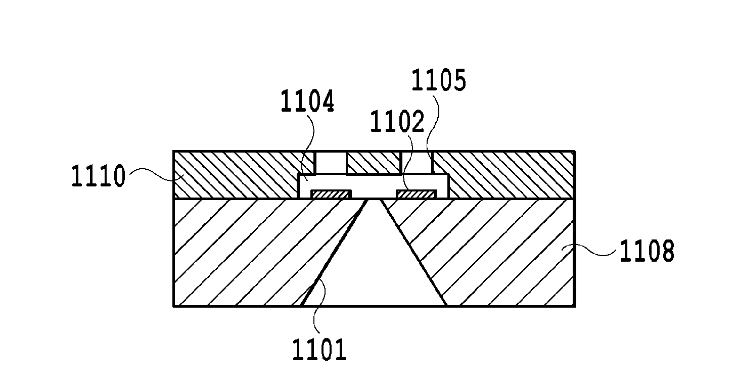
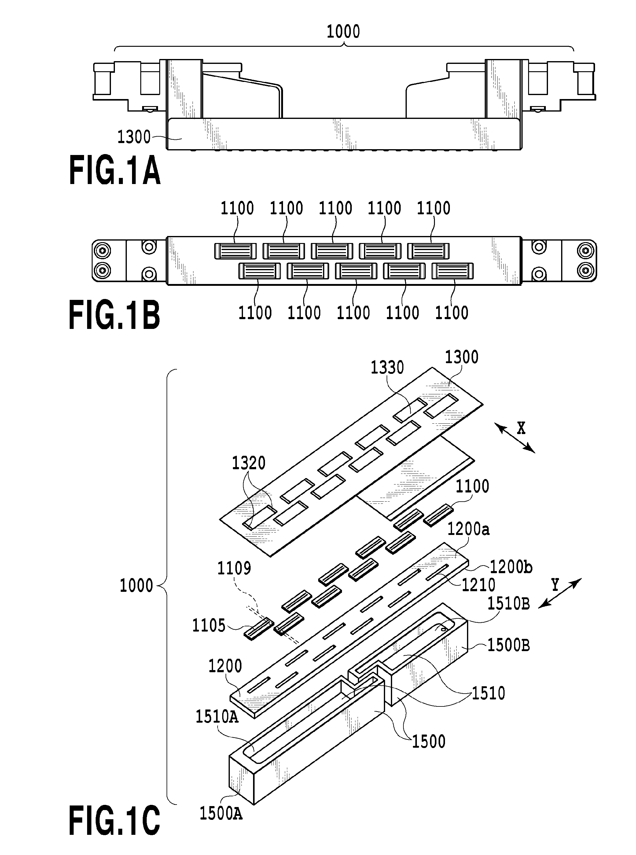
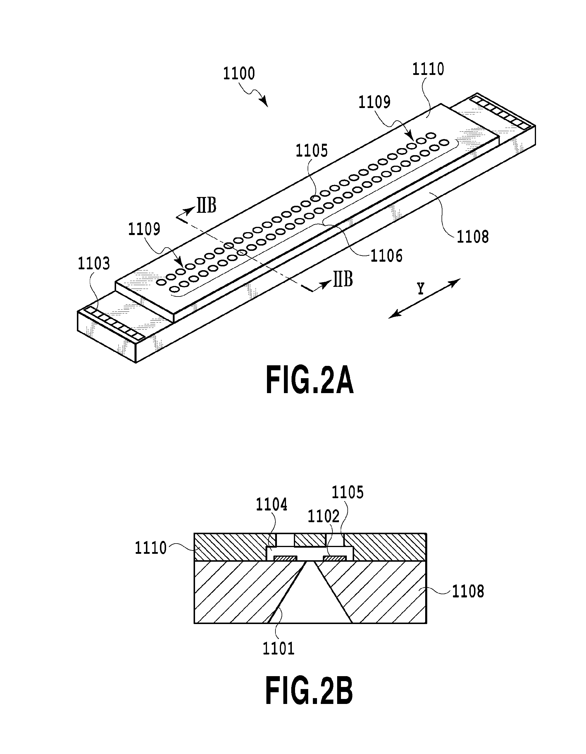
[0039]Hereinafter, a first embodiment of the present invention will be in detail explained with reference to the attached drawings. FIGS. 1A to 1C, FIG. 2A, FIG. 2B and FIG. 3 are explanatory diagrams explaining each of a preferred liquid ejection head and a preferred liquid ejection apparatus to which embodiments of the present invention are carried out or applied and a relationship of them. Hereinafter, each of the components in the liquid ejection head and the liquid ejection apparatus will be explained with reference to the attached drawings.

(Explanation of Liquid Ejection Head)

[0040]A liquid ejection head 1000 to which the embodiments of the present invention are applied is provided with an ejection opening line formed therein to cover a range of the maximum width of a sheet supposed to be used, and is a full line type liquid ejection head of an inkjet method that can perform a print in a wide range without the scanning of the liquid ejection head 1000. FIG. 1A to FIG. 1C are d...

Example

Second Embodiment

[0063]Hereinafter, an explanation will be made of a method for manufacturing a liquid ejection head according to a second embodiment of the present invention. It should be noted that since a basic configuration of the present embodiment is the same as that of the first embodiment, hereinafter only a characteristic configuration of the present embodiment will be explained.

[0064]FIG. 7A and FIG. 7B are diagrams showing a base plate to which the present embodiment is applicable, wherein the respective element substrates are arranged on a straight line to downsize a dimension of the liquid ejection head in the sheet conveying direction. The element substrate 1100 used herein is made to a diamond shape formed by obliquely cutting short sides of the element substrates 1100 neighbored to each other. Therefore also when the element substrates 1100 are arranged in a line, the element substrates 1100 can be arranged such that the end portions 1109 of the ejection opening grou...

Example

Third Embodiment

[0067]Hereinafter, an explanation will be made of a method for manufacturing a liquid ejection head according to a third embodiment of the present invention. It should be noted that since a basic configuration of the present embodiment is the same as that of the first embodiment, hereinafter only a characteristic configuration of the present embodiment will be explained.

[0068]FIG. 8A and FIG. 8B are diagrams showing a base plate to which the present embodiment is applicable, and an explanation will be made of the configuration of a liquid ejection head in which a plurality of ink supply slits 1201 are formed to a single element substrate 1100, that is, the configuration of a liquid ejection head that can deal with a plurality of colors. It should be noted that in the present embodiment, as shown in FIG. 8A, the ink supply slit 1210 comprises four ink supply slits that are arranged in parallel, but may comprise any numbers of ink supply slits as needed.

[0069]Since the...


PUM

PropertyMeasurementUnit
Lengthaaaaaaaaaa
Widthaaaaaaaaaa
Distanceaaaaaaaaaa

Abstract

There is provided a method for manufacturing a liquid ejection head comprising a base plate that is provided with supply slits, and an element substrate that is jointed to the base plate and is provided with supply openings. In a case where a shift amount between a position of the supply opening and a position of the supply slit is a predetermined value or more, the element substrate is corrected in position such that the shift amount is less than the predetermined value, and a position of the element substrate is corrected by an integral multiple of an image formation minimum pixel pitch in a sheet conveying direction, of an image formed on a sheet, as a unit of a travel distance at the correcting of the element substrate.

Description

BACKGROUND OF THE INVENTION[0001]1. Field of the Invention[0002]The present invention relates to a method for manufacturing a liquid ejection head composed of a line head in which element substrates provided with liquid supply openings are arranged in a direction crossing a sheet conveying direction on a base plate on which liquid supply slits are formed, for correcting a position of the liquid supply opening to the liquid supply slit, and the liquid ejection head.[0003]2. Description of the Related Art[0004]In general, in a liquid ejection head in which a plurality of element substrates are arranged, the element substrate is positioned and fixed on a support member (base plate) made of aluminum, resin or the like in such manner as to arrange the element substrate in a predetermined position at the time of attaching the liquid ejection head to a liquid ejection apparatus. In this way, there is used a line head in which ejection is made possible on a sheet over an entire region of a ...

Claims


Application Information

Patent Timeline
IPC IPC(8): B41J2/16
CPCB41J2/1632B41J2/155B41J2/1603B41J2/1623B41J2202/20Y10T29/49401
Inventor TAJIMA, HIROKI
Owner CANON KK
Why Eureka
Try Eureka