
Magnetic assembly and base thereof

Active Publication Date: 2019-02-28
DELTA ELECTRONICS INC
View PDF6 Cites 0 Cited by
  • Summary
  • Abstract
  • Description
  • Claims
  • Application Information

AI Technical Summary

Benefits of technology

The present invention provides a magnetic assembly and its base with different types of pins that can be used for both vertical and horizontal types of magnetic assemblies. This decentralizes production, reduces production costs, and standardizes the product. The pins can be placed in different directions to make it easier to solder and fix the windings, and the design can be tailored for different needs. The invention also includes a step between the frame and pin base, which allows for the magnetic core and windings to be partially disposed in the base, reducing the volume of the magnetic assembly and making it more space-efficient.

Problems solved by technology

However, in prior arts, the design of the base only can be applied to a single specific type of magnetic assemblies (i.e. the vertical type or the horizontal type), such that the base can not be shared, and fails to decentralize the production scale.
Furthermore, in order to meet the requirements of winding and solder, the volumes of the conventional bases are large, and the bases take up much space.

Method used


Image

  • Magnetic assembly and base thereof
  • Magnetic assembly and base thereof
  • Magnetic assembly and base thereof

Examples


Embodiment Construction

[0023]The present invention will now be described more specifically with reference to the following embodiments. It is to be noted that the following descriptions of preferred embodiments of this invention are presented herein for purpose of illustration and description only. It is not intended to be exhaustive or to be limited to the precise form disclosed.

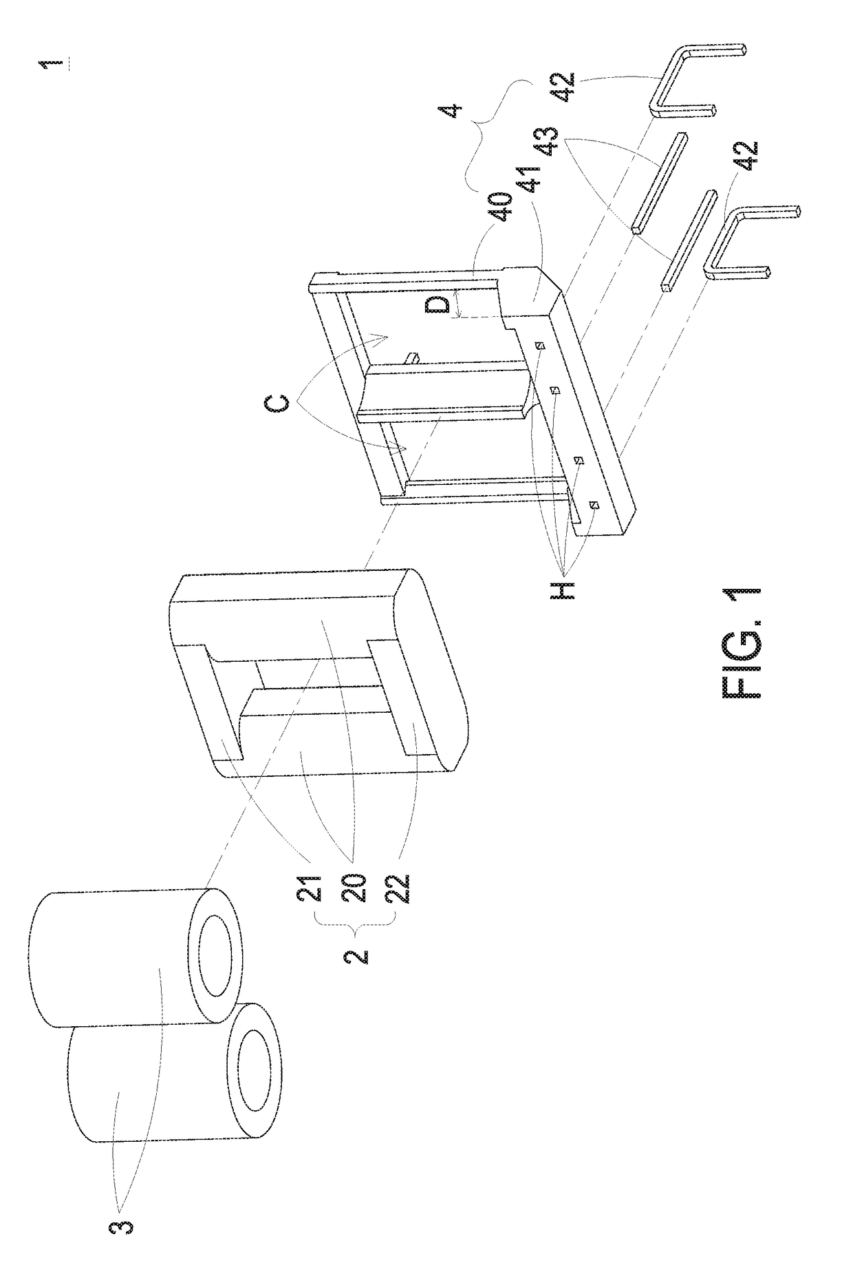
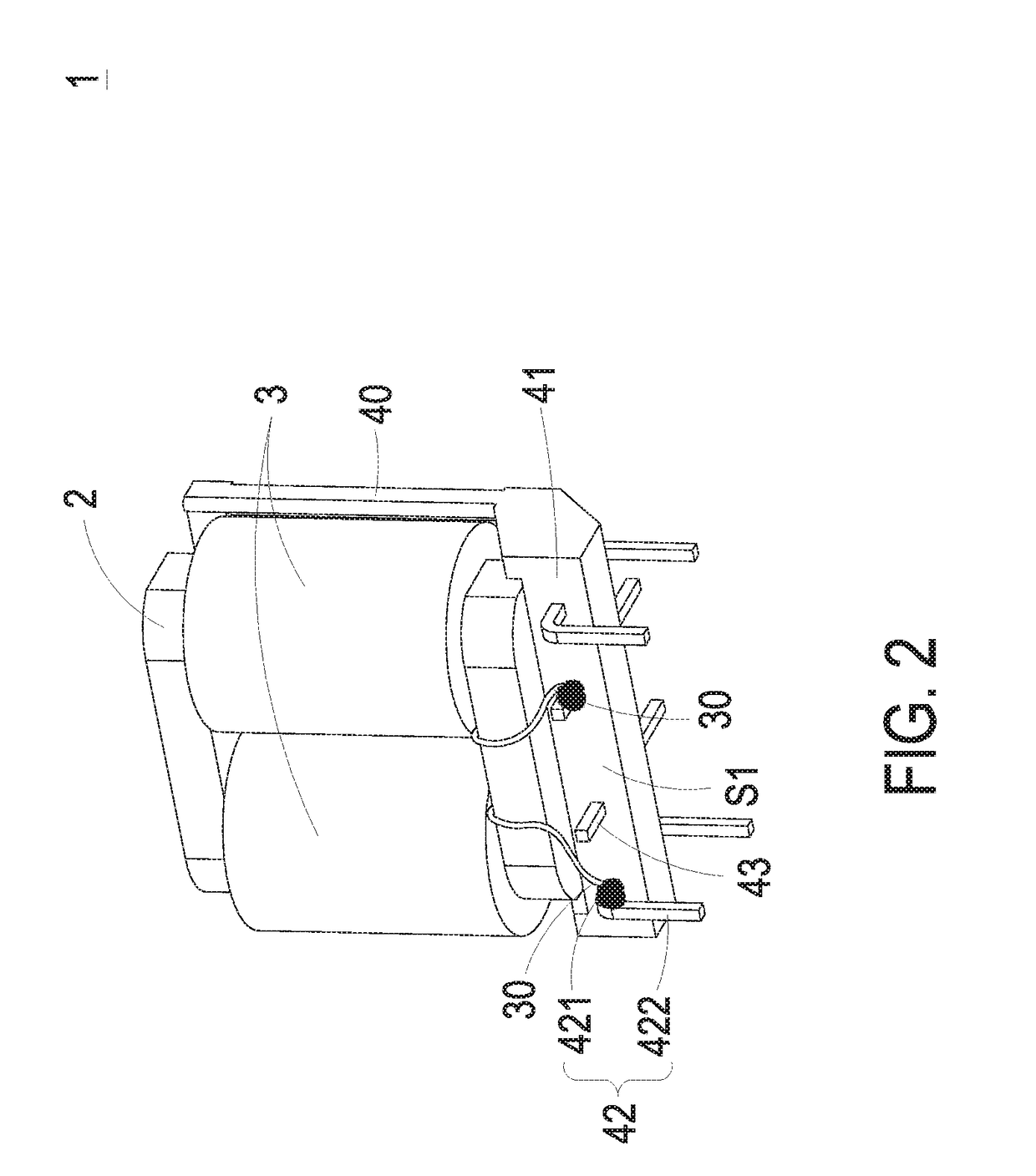
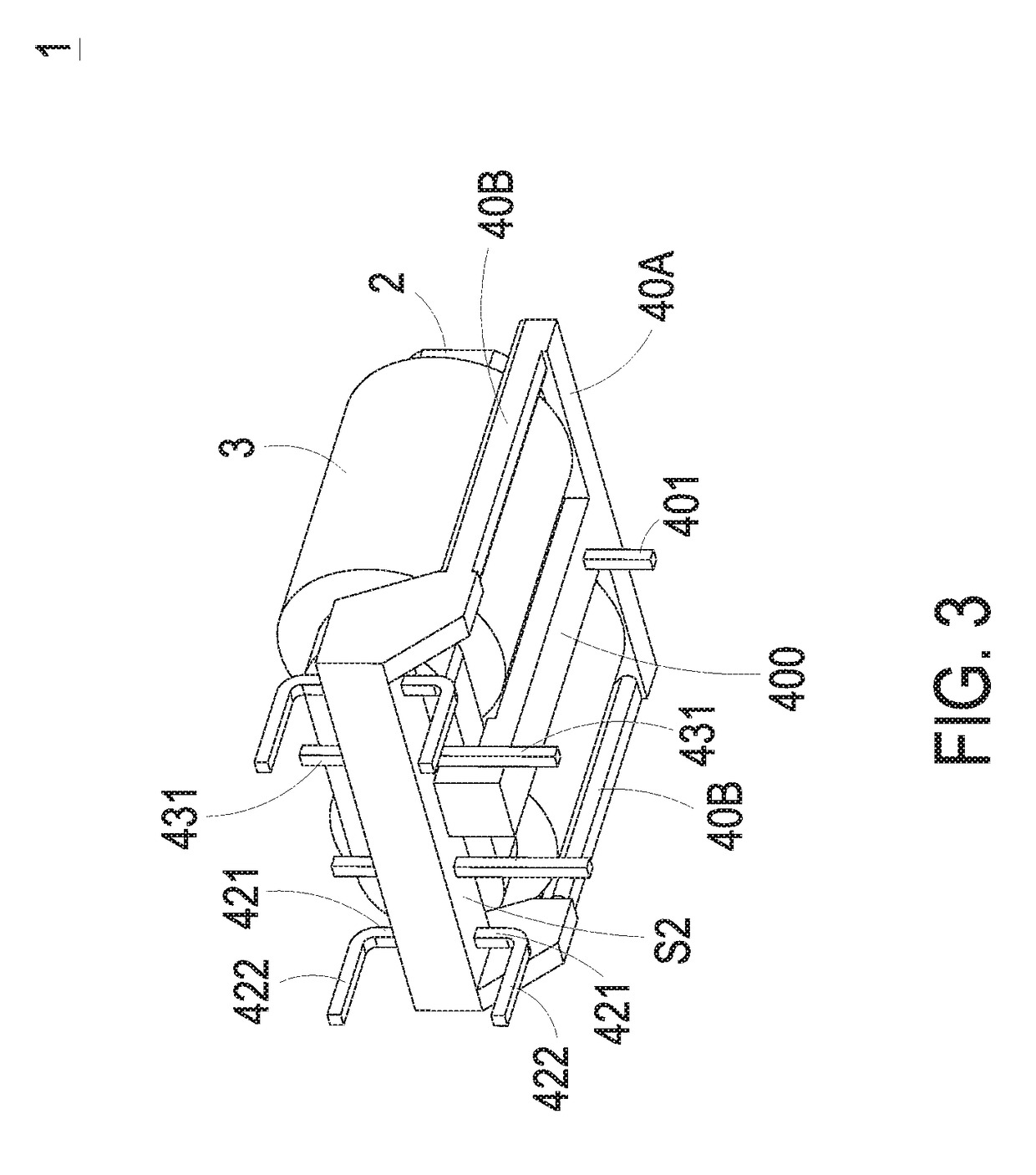
[0024]Please refer to FIG. 1, FIG. 2, FIG. 3, and FIG. 4. FIG. 1 schematically illustrates the exploded structure of a magnetic assembly according to an embodiment of the present invention. FIG. 2 schematically illustrates a side view of a magnetic assembly according to an embodiment of the present invention. FIG. 3 schematically illustrates another side view of the magnetic assembly as shown in FIG. 2. FIG. 4 schematically illustrates the structure of a magnetic assembly and a circuit board using the same according to an embodiment of the present invention. As shown in FIG. 1, FIG. 2, FIG. 3, and FIG. 4, the magnetic assembly 1 ...


PUM


Abstract

A magnetic assembly includes a magnetic core, two windings, and a base. The windings are arranged around the magnetic core, and each of the windings has two leading sections. The base carries the magnetic core, and comprises a frame part, a pin base, and two first pins and two second pins disposed on the pin base. The pin base is connected with the frame part, and has four through holes. Two first pins are disposed in two of the through holes, and two second pins are disposed in the other two of the through holes. Each of the first pins and the second pins has two extending parts extended from the first surface and the second surface respectively, and the leading sections of the windings are connected with the first pins and the second pins respectively. Therefore, the advantages of decreasing the production costs and product standardization are achieved.

Description

CROSS-REFERENCE TO RELATED APPLICATION[0001]This application claims priority from Taiwanese Patent Application No. TW 106212503, filed on Aug. 23, 2017, the entire contents of which are incorporated herein by reference for all purposes.FIELD OF THE INVENTION[0002]The present invention relates to a magnetic assembly and a base thereof, and more particularly to a base for mounting the magnetic assembly vertically or horizontally.BACKGROUND OF THE INVENTION[0003]With the advances in science and technology, a variety of electronic products are flourishing, and kinds of magnetic assemblies are used to satisfy the required circuit design in the electronic products. For example, by setting chokes or inductors, the electric energy in the circuit can be stored or released to regulate the current, thereby stabilizing the current in the circuit and filtering out the noise.[0004]In conventional magnetic assemblies, the windings are generally arranged around the magnetic cores and then mounted o...

Claims


Application Information

Patent Timeline
IPC IPC(8): H01F27/29H01F17/04H01F41/061
CPCH01F27/292H01F17/043H01F17/045H01F41/061H01F2027/297H01F2003/106H01F27/06H01F27/266H01F2027/065
Inventor PENG, HSIEN-CHUNYEN, CHUN-CHINGCHEN, KUN-TE
Owner DELTA ELECTRONICS INC
Learn More