
Downhole Separation Apparatus and Method

Active Publication Date: 2015-08-13
KLX ENERGY SERVICES
View PDF7 Cites 8 Cited by
  • Summary
  • Abstract
  • Description
  • Claims
  • Application Information

AI Technical Summary

Benefits of technology

This invention is a tool separation apparatus for use in drilling oil wells. Its design includes a collet body, a bottom sub, and a piston collet. The piston collet can move downward to release the collet body and the bottom hole assembly from the pipe string. The apparatus can withstand high fluid pressure and is easy to use. The technical effect of this invention is to provide a reliable and efficient tool separation apparatus for drilling oil wells.

Problems solved by technology

The shear pins of these devices may prematurely separate when the pipe of coiled tubing string is in the wellbore causing the unintended release of the attached tool or BHA.
A separated portion of a shear pin may also jam the release mechanism impeding or preventing, the release of the attached tool.
There is also the risk that a shear pin or a separated portion of a shear pin will stray into and remain in a lower or bottom sub portion of the separation device after separation from the pipe or coiled tubing string.
The hydraulic separation mechanisms of other such devices suffer from unreliable tool release mechanisms or require high pressures to release a tool from the pipe or coiled tubing string.

Method used


Image

  • Downhole Separation Apparatus and Method
  • Downhole Separation Apparatus and Method
  • Downhole Separation Apparatus and Method

Examples


Embodiment Construction

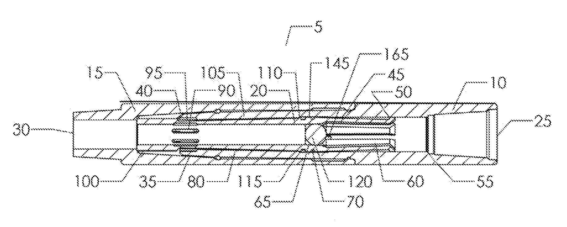
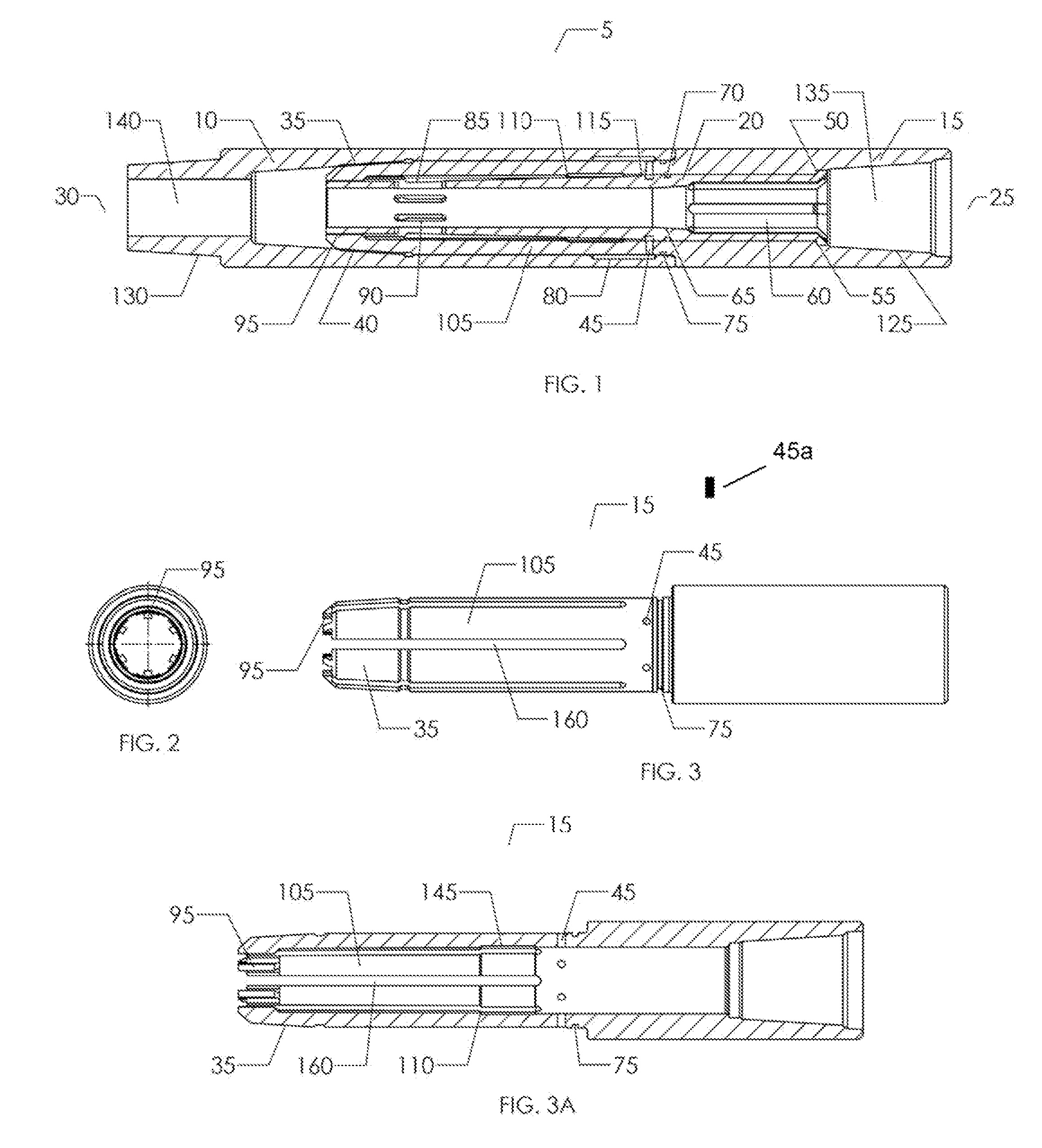
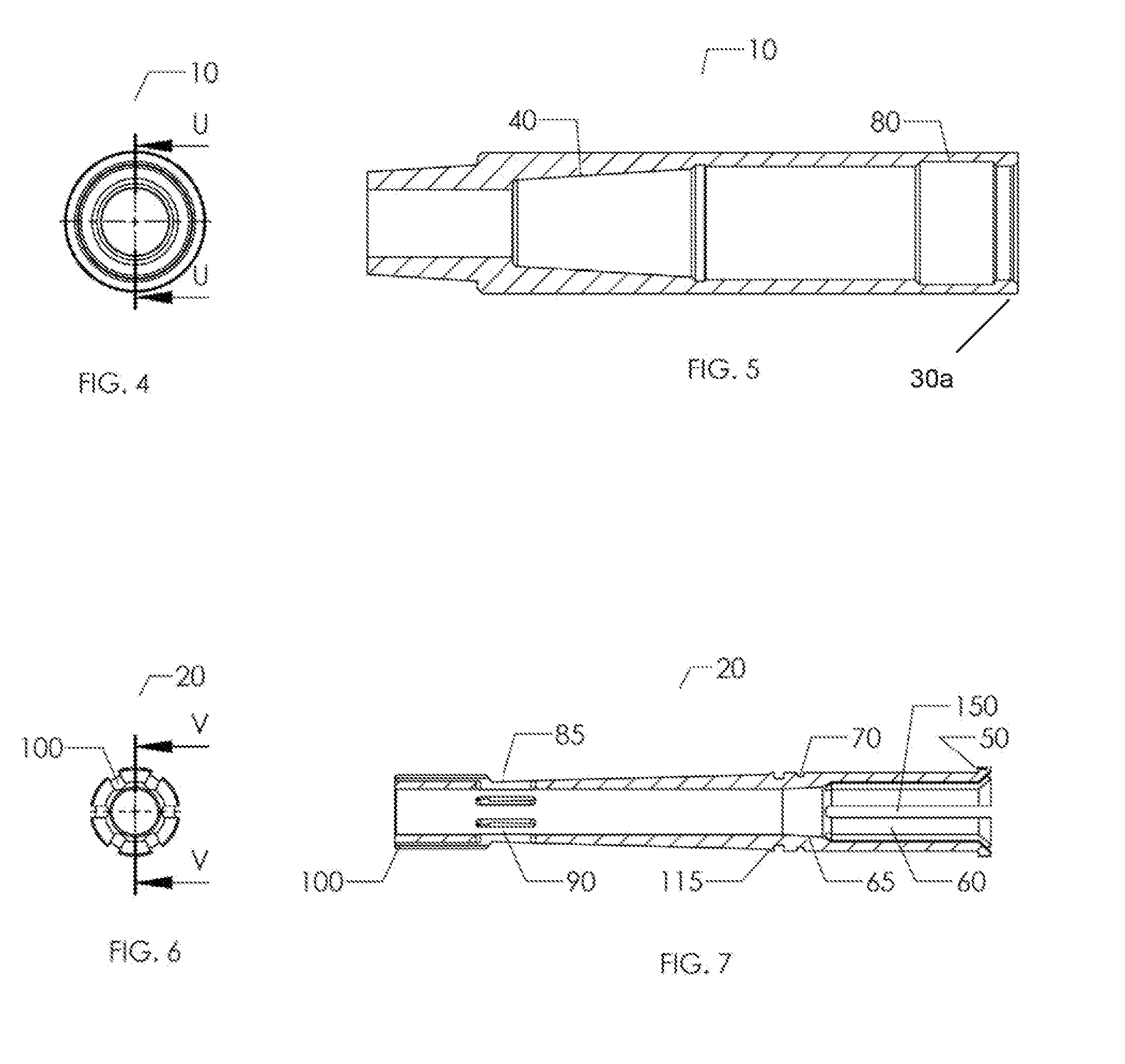
[0022]FIGS. 1-3 show an embodiment Of the downhole separation apparatus (5) of the present invention having hydraulic separation mechanism that provides a means to separate a pipe string comprising an upper pipe string portion. and a lower pipe string portion or bottom. bole assembly (BHA) should such a need arise. The apparatus (D) has an upper end (25) and lower end (30) configured for threadable attachment between a pipe string and a bottom hole assembly (BHA) deployed in a wellbore. The pipe string Will have a central bore through which fluid may be introduced and it may be comprised of a string of tubular pipe segments or it may be a coiled tubing suing. The apparatus (5) is positioned and threadably attached to the pipe string so that apparatus (5) will extend longitudinally along the longitudinal axis of the pipe string.

[0023]FIG. 1, a longitudinal cross-sectional view of the downhole separation apparatus (5), illustrates the position of the components of apparatus (5) in the...


PUM


Abstract

A downhole separation apparatus for releasing a pipe string from a bottom hole assembly is disclosed. The apparatus has a tubular collet body, a tubular bottom sub, and a piston collet positioned within the collet body. The collet piston has a plurality of collet fingers threadedly engaging an internal profile of the bottom sub. Separation is accomplished by pumping a circulation ball through the pipe string until it lands on a ball seat inside the collet piston. Increasing fluid pressure then shifts the piston collet axially downward within the collet body thereby causing the collet fingers to collapse to disengage the bottom hole assembly from the pipe string.

Description

PRIORITY[0001]This application claims priority to U.S. provisional application Ser. No. 61 / 937,222 filed Feb. 7, 2014 entitled “Downhole Separation Apparatus and Method”, the entire content of which is hereby incorporated by reference.FIELD OF THE INVENTION[0002]This invention pertains to downhole equipment for oil and gas wells. More particularly, it pertains to a downhole separation apparatus for use on a wellbore pipe string such as a coiled tubing string and., more particularly, this invention relates to an apparatus for separating the upper portion of a pipe string from the lower portion of the pipe string and bottom hole assembly or BHA.BACKGROUND OF THE INVENTION[0003]During the drilling, work over, or plug and abandonment of oil and gas producing wellbores, a variety of downhole tools may be attached to the lower portion or bottom hole assembly of a pipe or coiled tubing string. The attached tools are utilized to perform various functions within the wellbore and the bottom h...

Claims


Application Information

Patent Timeline
IPC IPC(8): E21B17/06E21B17/042E21B31/00E21B17/046
CPCE21B17/06E21B31/00E21B17/042E21B17/046
Inventor BAUDOIN, TOBY SCOTT
Owner KLX ENERGY SERVICES
Learn More